Mag-iwan ng Mensahe
Kung interesado ka sa aming mga produkto at gusto mong malaman ang higit pang mga detalye, mangyaring mag-iwan ng mensahe dito, sasagutin ka namin sa lalong madaling panahon.

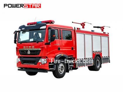
Manwal sa pagkukumpuni ng makina ng trak ng bumbero na 4HK1 ng Isuzu NPR
Ang Manwal sa Pagpapanatili ng Makina ng Isuzu Fire Truck 4HK1-TC, na tinatawag ding manwal sa pagkukumpuni ng makina. Isuzu fire tender o aklat ng Inhinyero Sasakyang pang-apula ng bumbero ng Isuzu .
Ang makinang Isuzu Fire Truck 4HK1-TC ay isang high-performance diesel engine na malawakang ginagamit sa mga fire truck, kilala sa pagiging maaasahan, tibay, at mataas na kahusayan nito. Upang matiyak ang pangmatagalang matatag na operasyon ng makina, mahalaga ang regular na pagpapanatili at pagkukumpuni. Maikling ipakikilala ng artikulong ito ang mga pangunahing nilalaman ng Manwal sa Pagpapanatili ng Makina ng Isuzu Fire Truck 4HK1-TC upang matulungan ang mga tauhan ng pagpapanatili na mas maunawaan at mapatakbo ito.
1. Pangkalahatang-ideya ng Makina
Ang 4HK1-TC engine ay isang 4-cylinder inline turbocharged diesel engine na may kapasidad na 5.2 litro at pinakamataas na lakas na 190 horsepower. Gumagamit ang makina ng advanced common rail fuel injection system at electronic control unit (ECU) upang makamit ang mas mataas na fuel efficiency at mas mababang emisyon.
2. Pang-araw-araw na Pagpapanatili
Ang pang-araw-araw na pagpapanatili ang batayan para matiyak ang normal na operasyon ng makina. Detalyadong inililista ng manwal ng pagpapanatili ang mga bagay na dapat gawin sa pang-araw-araw na inspeksyon, kabilang ang inspeksyon ng antas ng langis at coolant, paglilinis o pagpapalit ng air filter, pagpapalit ng fuel filter, atbp. Bukod pa rito, nagbibigay din ang manwal ng mga rekomendasyon para sa regular na pagpapalit ng langis ng makina at oil filter, kadalasan bawat 5,000 kilometro o bawat 6 na buwan.
3. Pagsusuri ng Mali
Ang manwal ng pagpapanatili ay naglalaman ng detalyadong proseso ng pag-diagnose ng depekto upang matulungan ang mga tauhan ng pagpapanatili na mabilis na mahanap at malutas ang mga problema. Inililista ng manwal ang mga karaniwang code ng depekto at ang mga kahulugan nito, at nagbibigay ng mga kaukulang solusyon. Halimbawa, kung ang makina ay mahina ang lakas, gagabayan ng manwal ang mga tauhan ng pagpapanatili upang suriin ang sistema ng gasolina, turbocharger at sistema ng tambutso, atbp.
4. Pagsasaayos at Pagpapalit ng mga Bahagi
Para sa mga makinang nangangailangan ng pagsasaayos o pagpapalit ng mga piyesa, ang manwal ng pagpapanatili ay nagbibigay ng detalyadong mga hakbang at pag-iingat. Halimbawa, kapag pinapalitan ang mga pangunahing bahagi tulad ng mga piston ring, valve guide at bearings, idedetalye ng manwal ang mga hakbang para sa pag-alis at pag-install, pati na rin ang mga kinakailangang kagamitan at mga detalye ng torque.
5. Mga Pag-iingat sa Kaligtasan
Binibigyang-diin ng manwal ng pagpapanatili ang kahalagahan ng ligtas na operasyon. Bago magsagawa ng anumang operasyon sa pagpapanatili, dapat mong tiyakin na ang makina ay ganap na pinalamig at ang suplay ng kuryente ay hindi na nakonekta. Bukod pa rito, nagbibigay din ang manwal ng mga rekomendasyon para sa paggamit ng personal na kagamitang pangproteksyon, tulad ng mga guwantes, salaming de kolor, at damit pangproteksyon.
Seksyon 1A
Sistema ng kontrol ng makina
Talaan ng mga Nilalaman
Pahina
[kung supportFields]> TALAAN NG MGA KASALUKUYAN \h \z \t "1A,1,1A-,2"
Sistema ng kontrol ng makina
[kung supportFields]>
4
[kung gte mso 9]>
Mga pag-iingat
[kung supportFields]>
4
[kung gte mso 9]>
Tungkulin at prinsipyo ng paggana
[kung supportFields]>
5
[kung gte mso 9]>
Diagram ng pagsasaayos ng mga bahagi
[kung supportFields]>
21
[kung gte mso 9]>
Dayagram ng sirkito
[kung supportFields]>
25
[kung gte mso 9]>
Paano matukoy ang depekto
[kung supportFields]>
42
[kung gte mso 9]>
Mga pamamaraan ng operasyon sa pag-diagnose ng depekto sa pamamagitan ng fault diagnostic meter
[kung supportFields]>
48
[kung gte mso 9]>
Pangkalahatang-ideya ng pagsusuri sa paggana
[kung supportFields]>
50
[kung gte mso 9]>
Pagtatanong
[kung supportFields]>
51
[kung gte mso 9]>
Pagsusuri sa sistema ng kontrol ng makina
[kung supportFields]>
53
[kung gte mso 9]>
Listahan ng datos ng metro ng diagnostic ng depekto
[kung supportFields]>
55
[kung gte mso 9]>
Mga nilalaman ng listahan ng datos ng metro ng diagnostic ng depekto
[kung supportFields]>
58
[kung gte mso 9]>
Output ng metro ng diagnostic ng depekto
[kung supportFields]>
64
[kung gte mso 9]>
Pagkabigo sa pagsisimula ng diagnostic meter ng depekto
[kung supportFields]>
65
[kung gte mso 9]>
Pagkabigo ng komunikasyon ng diagnostic meter ng depekto (sanggunian)
[kung supportFields]>
67
[kung gte mso 9]>
Pagkabigo sa komunikasyon sa ECM (sanggunian)
[kung supportFields]>
71
[kung gte mso 9]>
Pagkumpirma ng pagsisimula ng sistema
[kung supportFields]>
74
[kung gte mso 9]>
Kumpirmasyon ng sistema ng electrical circuit na nag-iilaw sa Engine MIL
[kung supportFields]>
77
[kung gte mso 9]>
Kumpirmasyon ng kumikislap na sistema ng electrical circuit ng Engine MIL
[kung supportFields]>
78
[kung gte mso 9]>
Inspeksyon ng sistema ng pagkontrol ng recirculation ng tambutso (EGR)
[kung supportFields]>
80
[kung gte mso 9]>
Inspeksyon ng sistema ng kontrol sa pag-init
[kung supportFields]>
84
[kung gte mso 9]>
Inspeksyon ng sistema ng pagkontrol ng paghihigpit sa preno ng tambutso/pasokan ng hangin
[kung supportFields]>
87
[kung gte mso 9]>
Pangkalahatang-ideya ng Diagnostic Trouble Code (DTC)
[kung supportFields]>
92
[kung gte mso 9]>
DTC P0016 (Flash code 16)
[kung supportFields]>
95
[kung gte mso 9]>
DTC P0087 (Flash code 225)
[kung supportFields]>
97
[kung gte mso 9]>
DTC P0088 (Flash code 118)
[kung supportFields]>
103
[kung gte mso 9]>
DTC P0089 (Flash code 151)
[kung supportFields]>
109
[kung gte mso 9]>
DTC P0091, P0092 (Flash code 247)
[kung supportFields]>
112
[kung gte mso 9]>
DTC P0093 (Flash code 227)
[kung supportFields]>
116
[kung gte mso 9]>
DTC P0107, P0108 (Flash code 32)
[kung supportFields]>
122
[kung gte mso 9]>
DTC P0112, P0113 (Flash code 22)
[kung supportFields]>
127
[kung gte mso 9]>
DTC P0117, P0118 (Flash code 23)
[kung supportFields]>
132
[kung gte mso 9]>
DTC P0122, P0123 (Flash code 43)
[kung supportFields]>
137
[kung gte mso 9]>
DTC P0182, P0183 (Flash code 211)
[kung supportFields]>
142
[kung gte mso 9]>
DTC P0192, P0193 (Flash code 245)
[kung supportFields]>
147
[kung gte mso 9]>
[kung supportFields]> DTC P0201, P0202, P0203, P0204 (Flash code 271,272,273,274)................................................... 1A-157
DTC P0217 (Flash code 542)......................................................................................................... 1A-170
DTC P0219 (Flash code 543)......................................................................................................... 1A-172
DTC P0234 (Flash code 42)......................................................................................................... 1A-175
DTC P0299 (Flash code 65)......................................................................................................... 1A-178
DTC P0335 (Flash code 15)......................................................................................................... 1A-182
DTC P0336 (Flash code 15)......................................................................................................... 1A-187
DTC P0340 (Flash code 14)......................................................................................................... 1A-190
DTC P0341 (Flash code 14)......................................................................................................... 1A-195
DTC P0380 (Flash code 66)......................................................................................................... 1A-198
DTC P0381 (Flash code 67)......................................................................................................... 1A-201
DTC P0404 (Flash code 45)......................................................................................................... 1A-205
DTC P0409 (Flash code 44)......................................................................................................... 1A-208
DTC P0477, P0478 (Flash code 46)......................................................................................... 1A-212
DTC P0500 (Flash code 25)......................................................................................................... 1A-216
DTC P0502, P0503 (Flash code 25)......................................................................................... 1A-218
DTC P0563 (Flash code 35)......................................................................................................... 1A-223
DTC P0601 (Flash code 53)......................................................................................................... 1A-225
DTC P0602 (Flash code 154)......................................................................................................... 1A-226
DTC P0604, P0606, P060B (Mga Flash code 153, 51, 36)................................................................. 1A-228
DTC P0641 (Flash code 55)......................................................................................................... 1A-230
DTC P0650 (Flash code 77)......................................................................................................... 1A-233
DTC P0651 (Flash code 56)......................................................................................................... 1A-237
DTC P0685, P0687 (Flash code 416).......................................................................................... 1A-241
DTC P0697 (Flash code 57)......................................................................................................... 1A-245
DTC P1093 (Flash code 227)......................................................................................................... 1A-248
DTC P1261, P1262 (Flash code 34)......................................................................................... 1A-253
DTC P1404 (Flash code 45)......................................................................................................... 1A-255
DTC P1621 (Flash code 54)......................................................................................................... 1A-257
DTC P2122, P2123 (Flash code 121)......................................................................................... 1A-258
DTC P2127, P2128 (Flash code 122)......................................................................................... 1A-264
DTC P2138 (Flash code 124)......................................................................................................... 1A-270
DTC P2146, P2149 (Flash code 158).......................................................................................... 1A-273
DTC P2228, P2229 (Flash code 71)......................................................................................... 1A-279
DTC P253A (Flash code 28)......................................................................................................... 1A-284
DTC P256A (Flash code 31)......................................................................................................... 1A-287
DTC U0073 (Flash code 84)......................................................................................................... 1A-291
Pagsusuri ng Sintomas................................................................................................................ 1A-296
Kababalaghan: Intermittence........................................................................................................ 1A-297
Sintomas: Mahirap magsimula......................................................................................... 1A-300
Mga Kababalaghan: Surge, hindi matatag na idling o pagtigil ng makina......................................................................... 1A-303
Mga Kababalaghan: Mataas na bilis ng pag-idle................................................................................................ 1A-306
Sintomas: Pang-emerhensiyang paghinto......................................................................................... 1A-307
Sintomas: Pagbabago sa emerhensiya......................................................................................... 1A-309
Sintomas: Mahina ang makina, pagkabigo ng acceleration o pagkaantala ng pagtugon......................................................................... 1A-311
Mga Penomeno: Paulit-ulit na operasyon, pagkabigo ng acceleration......................................................................... 1A-314
Sintomas: Ingay ng pagkasunog......................................................................................................... 1A-316
Sintomas: Mababa ang kahusayan sa pagtitipid ng gasolina......................................................................... 1A-317
Mga Penomeno: itim na usok mula sa tambutso......................................................................................... 1A-319
Sintomas: Puting usok mula sa tambutso................................................................................. 1A-321
Pangunahing mga parametro ng sensor......................................................................................................... 1A-323
Mga espesyal na kagamitan......................................................................................................................... 1A-325
Programa............................................................................................................... 1A-326
Panuntunan sa pagprograma...................................................................................................................... 1A-326
Programa............................................................................................................... 1A-326
Pagkatuto sa bombang iniksyon......................................................................................................... 1A-328
Pagsasaayos......................................................................................................................... 1A-328
Paggamit ng mga kagamitan sa pagsubok ng circuit
Sa kaso ng diagnosis ayon sa programang diagnostics, huwag gamitin ang test lamp para sa diagnosis ng power train electrical system maliban kung may ibang tinukoy. Kung sakaling ang probe terminal ang gagamitin para sa programang diagnostic, mangyaring gamitin ang terminal testing adapter kit na 5-8840-2835-0.
Magagamit na bahaging elektrikal sa merkado
Ang mga piyesang elektrikal na available sa merkado ay nangangahulugang mga piyesang elektrikal na binibili mula sa merkado upang i-install sa sasakyan. Dahil ang mga piyesang ito ay hindi isinasaalang-alang sa yugto ng disenyo ng sasakyan, bigyang-pansin ang mga ito kapag ginagamit ang mga piyesang ito.
Pag-iingat:
Ang magagamit na kuryente at ground ng mga de-koryenteng bahagi sa merkado ay dapat na konektado sa circuit nang hindi nakabatay sa electrical control system circuit.
Bagama't maaaring gamitin ang mga de-kuryenteng bahagi na makikita sa merkado, maaaring magdulot ito ng depekto sa paggana ng electrical control system sa ilang mga kaso. Kabilang dito ang mga aparatong hindi nakakonekta sa electrical system, halimbawa, ang mobile phone, radyo. Samakatuwid, sa power train diagnosis, suriin muna kung naka-install na ang mga de-kuryenteng bahaging makikita sa merkado. Kung gayon, alisin ang mga ito sa sasakyan. Kung mayroon pa ring depekto pagkatapos matanggal ang bahagi, sundin ang pangkalahatang proseso para sa diagnosis.
Pinsala dahil sa ESD
Dahil ang mga elektronikong bahagi sa electrical control system ay maaaring gumana sa ilalim ng napakababang boltahe, ang mga ito ay madaling masira dahil sa ESD. Ang ilang elektronikong bahagi ay nasisira ng static electricity na mas mababa sa 100V na hindi gaanong kapansin-pansin sa tao. Ang kapansin-pansing ESD ng tao ay nangangailangan ng 4000V na boltahe. Sa maraming pagkakataon, ang tao ang nagdadala ng static electricity, kung saan ang friction at induction electrification ang pinakakaraniwan.
● Kapag ang tao ay gumalaw nang patagilid sa upuan, ito ay lilikha ng frictional electrification.
● Kapag ang taong nakasuot ng sapatos na may insulasyon ay malapit sa bagay na may mataas na kuryente, ang electrostatic induction ay magaganap sa sandaling mahawakan ng tao ang lupa. Ang tao ay makuryente kapag ang mga karga na may parehong polarity ay nagtatagpo sa mga karga na may magkasalungat na polarity. Dahil ang static electricity ay magdudulot ng pinsala, maingat na hawakan ang mga elektronikong bahagi at subukan ang mga ito.
Pag-iingat:
Sundin ang mga sumusunod na tuntunin upang maiwasan ang pinsala dulot ng ESD:
● Huwag hawakan ang mga pin ng contact ng terminal ng ECM at mga elektronikong bahagi na naka-solder sa back plate ng ECM circuit.
● Huwag i-unpack ang mga lalagyan maliban kung tapos na ang paghahanda para sa pag-install ng mga piyesa.
● Ikabit ang pakete at ang sasakyan sa normal na ground bago alisin ang mga piyesa mula sa pakete.
● Kung gumagalaw nang patagilid sa upuan, o nakaupo mula sa nakatayong postura o ginagamit ang bahagi habang gumagalaw sa isang tiyak na distansya, siguraduhing nahawakan ang normal na lupa bago i-install ang bahagi.
Tungkulin at prinsipyo ng paggana
Sistema ng pagkontrol ng makina (karaniwang riles)
Pangkalahatang-ideya at mga detalye ng sistema
Ang sistema ng pagkontrol ng makina ay nangangahulugang sistemang elektrikal na kontrol upang kontrolin ang makina sa pinakamainam na estado ng pagkasunog ayon sa kondisyon ng pagmamaneho. Binubuo ito ng mga sumusunod na bahagi:
● Sistema ng iniksyon ng gasolina na kinokontrol ng elektroniko (uri ng common rail)
● EGR
Bukod pa rito, kasama sa sistema ng pagkontrol ng makina ang mga sumusunod na tungkulin sa pagkontrol ng sistema.
● Sistema ng kontrol sa pag-init
● Umiikot na output ng makina
● Tungkulin sa komunikasyon at pagsusuri sa sarili
[endif]
[kung gte vml 1]>
Sistema ng iniksyon ng gasolina na kinokontrol ng elektroniko (uri ng common rail)
Ang common rail system ay mayroong pressure chamber at injector. Ang pressure chamber ay dinisenyo upang mag-imbak ng pressurized fuel at tinatawag na common rail; ang injector ay mayroong electronic control solenoid valve upang mag-inject ng pressurized fuel sa combustion chamber. Dahil ang injection control (ang injection pressure, injection rate at injection time) ay kinokontrol ng ECM, pinapayagan ng common rail system ang malayang pagkontrol sa bilis at load ng makina. Kahit na mababa ang bilis ng makina, mapapanatili ang matatag na injection pressure, na lubos na makakabawas sa partikular na itim na usok kapag pinaandar at pinabilis ang diesel engine. Sa pamamagitan ng kontrol na ito, ang tambutso ay magiging malinis, ang volume ng tambutso ay magiging mas kaunti at ang output ay magiging mas mataas.
Kontrol ng dami ng iniksyon
Kinokontrol nito ang winding ng injector ayon sa signal na nakuha mula sa bilis ng makina at pagbukas ng pedal ng accelerator at dahil dito ay kinokontrol ang volume ng iniksyon ng gasolina upang makamit ang pinakamahusay na volume.
Kontrol ng presyon ng iniksyon
Para payagan ang high pressure injection kahit na mababa ang bilis ng makina, dapat kontrolin ang pressure ng gasolina sa loob ng common rail. Kalkulahin ang naaangkop na pressure sa common rail ayon sa bilis ng makina at dami ng fuel injection, ilabas ang tamang dami ng gasolina sa pamamagitan ng control injection pump at ipasok ito sa common rail na nasa ilalim ng pressure.
Kontrol sa oras ng iniksyon
Pinapalitan nito ang timing function at kinakalkula ang naaangkop na oras ng fuel injection ayon sa bilis ng makina at dami ng injection at pagkatapos ay kinokontrol ang injector.
Kontrol sa bilis ng iniksyon
Para mapahusay ang kahusayan ng pagkasunog ng silindro, mag-inject (bago ang pag-iiniksyon) ng kaunting gasolina para sa ignisyon. Pagkatapos ng ignisyon, isagawa ang pangalawang pag-iiniksyon (pangunahing iniksyon). Kontrolin ang oras ng pag-iiniksyon at dami ng iniiniksyon sa pamamagitan ng injector (ang injector coil).
 [endif]
Sistema ng Panggatong
Ang common rail system ay binubuo ng 2 fuel pressure system.
● Linya ng pasukan na may mababang presyon: sa pagitan ng tangke ng gasolina at injection pump
● Linya ng mataas na presyon: sa pagitan ng injection pump at injector
Ang gasolina ay hinihigop papunta sa injection pump mula sa tangke ng gasolina at pinapalakas sa bomba upang magsuplay sa common rail. Sa puntong ito, Kinokontrol ng signal mula sa ECM ang suction control valve (ang common rail pressure regulator) upang kontrolin ang dami ng gasolina na ibinibigay sa common rail.
Dayagram ng sistema ng gasolina
[kung gte vml 1]>
|
Susi 1. Karaniwang Riles 2. Balbula na naglilimita sa presyon 3. Tubong pabalik ng injector 4. Pang-injektor 5. Tubo ng pagbabalik ng gasolina 6. Tubo ng suplay ng gasolina |
7. Tangke ng gasolina 8. Balbula ng paghinga 9. Bomba ng panimulang bahagi 10. Pansala ng gasolina (may panghiwalay ng langis at tubig) 11. Balbula ng pagbabalik 12. Bomba ng iniksyon ng gasolina |
EGR (Muling sirkulasyon ng tambutso)
Nirerecycle ng Egr system ang isang bahagi ng exhaust gas papunta sa intake manifold at dahil dito ay binabawasan ang nitrogen oxides (NOx) emission. Sa pamamagitan ng EGR system, makakamit ang driving operability at pagbawas ng exhaust gas emission. Kinokontrol ng control current mula sa EGR ang solenoid valve para gumana at dahil dito ay kinokontrol ang EGR valve lift. Bukod pa rito, nade-detect ng sistemang ito ang aktwal na valve lift gamit ang EGR position sensor upang maisakatuparan ang pinong kontrol sa EGR.
Magsisimulang gumana ang EGR kapag natugunan na ang mga kondisyon ng bilis ng makina, temperatura ng coolant ng makina, temperatura ng intake, at barometric pressure. Pagkatapos, kalkulahin nito ang bukana ng balbula ayon sa bilis ng makina at target na dami ng fuel injection. Batay sa kinakalkulang bukana ng balbula, tinutukoy nito ang load ng solenoid valve drive at pagkatapos ay pinapaandar ang balbula. Papatayin ang air intake throttle habang ginagamit ang EGR upang maabot ng inside pressure ng intake manifold ang target na halaga.
[kung gte vml 1]>
[endif]
[kung !mso]
|
[endif]
[kung !mso]
|
[endif]
[kung !mso]
|
[endif]
[kung !mso]
|
|
Susi 1. ECM 2. Sensor ng posisyon ng EGR 3. Balbula ng EGR 4. Palamigan ng EGR |
5. Balbula ng throttle ng paggamit
|
Kontrol sa pag-init
Sistema ng kontrol sa pag-init
Ang sistema ng pagkontrol sa pag-init ay dinisenyo upang mapadali ang pag-start ng makina sa mababang temperatura at mabawasan ang puting usok at ingay. Kapag aktibo ang starter switch, tinutukoy ng ECM ang temperatura ng coolant ng makina ayon sa signal mula sa engine coolant temperature (ECT) sensor upang ayusin ang oras ng pag-init at makamit ang naaangkop na mga kondisyon sa pag-start para sa makina. Bukod pa rito, ang natitirang init ng pag-init ay maaaring mapanatili ang stable na idle. Ang ECM ang nagpapasya sa oras ng pag-init ayon sa temperatura ng coolant ng makina upang paandarin ang warming-up relay at indicator lamp.
[endif]
[kung gte vml 1]>
Pangkalahatang-ideya ng kontrol ng preno ng tambutso
Ang tubo ng tambutso ng preno ng tambutso ay may balbula sa loob. Ang pagsasara ng balbula ay maaaring magpataas ng resistensya sa stroke ng tambutso at mapahusay ang epekto ng preno ng makina. Ang balbula ng preno ng tambutso ay gumagana ayon sa presyon ng vacuum. Ang presyon ng vacuum ng preno ng tambutso ay kinokontrol ng pagbukas at pagsara ng solenoid valve. Pagaganahin ng ECM ang solenoid valve kung ang bilis ng makina ay higit sa 575rpm at natutugunan ang lahat ng mga kondisyon ng pagpapatakbo ng preno ng tambutso.
Mga kondisyon ng pagpapatakbo ng preno ng tambutso
● Naka-on ang switch ng preno ng tambutso
● Hindi naka-pindot ang pedal ng accelerator
● Hindi nade-detect ang abnormal na posisyon ng accelerator pedal (APP) sensor, abnormal na exhaust brake circuit, abnormal na clutch switch, abnormal na APP sensor switch, abnormal na A/D switch, atbp.
● Hindi naka-depress ang pedal ng clutch
● Boltahe ng sistema na higit sa 24V
● Lampas sa tinukoy na saklaw ang bilis ng sasakyan
ECM
Pangkalahatang-ideya ng ECM
[kung gte vml 1]>
Binabantayan ng ECM ang impormasyon mula sa bawat sensor sa lahat ng oras upang makontrol ang power train. Ginagawa ng ECM ang function ng system diagnostic upang matukoy ang problema sa operasyon ng system, ipaalala sa driver ang MIL sa pamamagitan ng engine at itala ang DTC nang sabay. Tinutukoy ng DTC ang trouble zone upang matulungan ang maintenance man.
Mga tungkulin ng ECM
Naglalabas ang ECM ng 5V na boltahe upang paganahin ang iba't ibang sensor at switch. Gayunpaman, dahil ang kuryente ay ibinibigay ng resistance ng ECM, ang test lamp na konektado sa circuit ay hindi magbubukas kahit na napakataas ng resistance. Sa ilang mga kaso, hindi maipapakita ng karaniwang voltmeter ang tamang pagbasa dahil masyadong mababa ang resistance nito. Upang maipakita ang tamang pagbasa, siguraduhing gamitin ang digital multimeter na may input impedance na 10MΩ nang hindi bababa sa (5-8840-2691-0). Kinokontrol ng ECM ang ground circuit o power circuit sa pamamagitan ng transistor o iba pang unit at dahil dito ay kinokontrol ang output circuit.
Mga bahagi ng ECM at komposisyon
Kayang makamit ng ECM ang mataas na kakayahang magmaneho at kahusayan sa gasolina habang pinapanatili ang tinukoy na tambutso ng gas. Sinusubaybayan ng ECM ang pagganap ng makina at sasakyan sa pamamagitan ng crankshaft position (CKP) sensor at vehicle speed sensor (VSS) atbp.
Paglalarawan ng boltahe ng ECM
Inilalapat ng ECM ang karaniwang boltahe sa bawat switch at sensor. Ito ay dahil napakataas ng resistensya ng ECM habang mababa ang boltaheng inilalapat sa circuit. Hindi umiilaw ang test lamp kahit na nakakonekta sa circuit. Dahil napakababa ng input impedance ng voltmeter na karaniwang ginagamit ng maintenance man, kung minsan ay hindi maipapakita ng voltmeter ang tamang pagbasa. Sa ganitong kaso, gumamit ng digital multimeter na may 10MΩ input impedance (5-8840-2691-0) upang makuha ang tamang pagbasa ng boltahe.
Ang ECM input/output unit ay may analog-digital converter, signal damping, counter at special actuator. Maaaring kontrolin ng ECM ang karamihan sa mga bahagi ng komposisyon sa pamamagitan ng electronic switch.
EEPROM
Ang EEPROM ay isang permanenteng storage chip na naka-solder sa ECM back plate. Upang makontrol ang power train, ipinapadala ng ECM ang kinakailangang programa at mensahe ng pagkakalibrate sa EEPROM.
Hindi ito maaaring palitan ng ROM, kaya hindi na maaaring palitan ang EEPROM. Kung may matuklasan na abnormal na EEPROM, direktang palitan ang ECM.
Mga Pagsasaalang-alang para sa Pagkukumpuni ng ECM
Kayang tiisin ng ECM ang pangkalahatang kuryenteng may kaugnayan sa pagmamaneho ng sasakyan. Huwag hayaang mag-overload ang circuit. Sa panahon ng open circuit at short circuit test, huwag ikonekta ang ECM circuit sa ground wire o maglagay ng boltahe maliban kung may ibang tinukoy. Para sa mga ganitong circuit test, siguraduhing gamitin ang digital multimeter (5-8840-2691-0).
 [endif]
Ang injection pump ang pangunahing bahagi ng common rail electronic fuel injection system. Ang injection pump ay naka-install sa harap ng makina. Ang common rail pressure regulator at fuel temperature (FT) sensor ang mga bahagi ng komposisyon ng injection pump.
Ang gasolina ay ipinapasok sa injection pump mula sa tangke ng gasolina sa pamamagitan ng inside supply pump (uri ng rotor). Ang supply pump ay nagpapapasok ng gasolina sa 2 plunger compartment sa injection pump. Ang gasolina na ipinapasok sa plunger compartment ay kinokontrol ng common rail pressure regulator. Ang common rail pressure regulator ay kinokontrol lamang ng ECM supply current. Ang daloy ng gasolina ay aabot sa pinakamataas kung walang kuryenteng ipinapasok sa solenoid valve. Sa kabaligtaran, ang gasolina ay titigil sa pag-agos kapag ang daloy ng solenoid valve ay umabot sa pinakamataas. Habang umiikot ang makina, ang dalawang plunger ay bumubuo ng mataas na presyon sa common rail. Kinokontrol nito ang common rail pressure regulator ayon sa signal ng ECM at dahil dito ay kinokontrol ang dami at presyon ng gasolina sa common rail. Sa ganitong paraan, ang pinakamainam na estado ng pagpapatakbo ay maaaring makamit upang mapahusay ang kahusayan sa ekonomiya ng gasolina at mabawasan ang emisyon ng NOx.
[kung gte vml 1]>
Susi
1. Sensor ng temperatura ng gasolina (FT)
2. Balbula ng kontrol sa pagsipsip (regulador ng presyon ng karaniwang riles)
Balbula ng kontrol sa pagsipsip (regulador ng presyon ng karaniwang riles)
Kinokontrol ng ECM ang load factor ng common rail pressure regulator (ang oras ng pag-on ng common rail pressure regulator) upang i-regulate ang dami ng gasolina na ipinapasok sa high pressure plunger. Upang makamit ang ninanais na presyon ng rail, ipasok ang tamang dami ng gasolina upang mabawasan ang drive load ng injection pump. Kapag ang kuryente ay ipinapasok sa common rail pressure regulator, ang variable electromotive force na naaayon sa load factor ay mabubuo upang baguhin ang pagbukas ng fuel line at dahil dito ay isaayos ang dami ng gasolina. Kapag ang common rail pressure regulator ay pinatay, ang retracting spring ay aatras, ang fuel line ay ganap na magbubukas at ang gasolina ay dadaloy sa plunger (ang maximum intake at maximum discharge). Kapag bukas ang common rail pressure regulator, ang fuel line ay magsasara (normally open) sa ilalim ng function ng retracting spring. Sa pamamagitan ng pagbukas at pagsara ng common rail pressure regulator, ang gasolina na naaayon sa working load rate ay ibibigay at pagkatapos ay ilalabas mula sa plunger.
Sensor ng temperatura ng gasolina (FT)
Ang FT sensor ay ikinakabit sa injection pump at binabago ng thermistor ang resistance kasabay ng pagbabago ng temperatura. Ang resistance ay magiging mababa kung ang temperatura ng gasolina ay mataas at mataas kung ang temperatura ng gasolina ay mababa. Ang ECM ay naglalapat ng 5V na boltahe sa FT sensor sa pamamagitan ng load resistor at kinakalkula ang temperatura ng gasolina ayon sa pagbabago ng boltahe upang makontrol ang injection pump. Ang boltahe ay magiging mababa kung ang resistance ay mababa (ang temperatura ay mataas) at mataas kung ang resistance ay mataas (ang temperatura ay mababa).
Karaniwang riles
[kung gte vml 1]>
Susi
1. Balbula na naglilimita sa presyon
2. Sensor ng presyon ng karaniwang riles
Dahil sa common rail type electrical control fuel injection system, ang common rail ay nasa pagitan ng injection pump at injector upang iimbak ang high pressure fuel. Ang pressure sensor at pressure limiting valve ay naka-install sa common rail. Nade-detect ng pressure sensor ang fuel pressure sa common rail at ipinapadala ang signal sa ECM. Batay sa signal na ito, kinokontrol ng ECM ang fuel pressure sa common rail gamit ang injection pump common rail pressure regulator. Kung ang common rail sa loob ng fuel pressure ay masyadong mataas, ang pressure limiting valve ay magbubukas upang palabasin ang pressure.
Sensor ng presyon ng karaniwang riles
Ang common rail pressure sensor ay nakakabit sa common rail upang matukoy ang presyon ng gasolina sa rail at i-convert ang presyon sa boltaheng signal. Kung mas mataas ang presyon, mas mataas ang boltahe; kung mas mababa ang presyon, mas mababa ang boltahe. Kinakalkula ng ECM ang aktwal na presyon ng common rail (ang presyon ng gasolina) ayon sa boltaheng signal mula sa sensor upang makontrol ang fuel injection.
Balbula na naglilimita sa presyon
[kung gte vml 1]>
Susi
1. Balbula
2. Katawan ng balbula
3. Gabay ng balbula
4. Tagsibol
5. Pabahay
6. Pasok ng gasolina
7. Lalagyan ng gasolina
Sa kaso ng abnormal na mataas na presyon, ang pressure limiting valve ay magbubukas upang palabasin ang presyon. Ang balbula ay magbubukas kapag ang common rail inside pressure ay lumampas sa 220MPa at magsasara kapag ang presyon ay mas mababa sa 50MPa. Ang gasolinang inilalabas mula sa pressure limiting valve ay dadaloy patungo sa tangke ng gasolina.
Injector
[kung gte vml 1]>
Susi
1. Boltahe ng kable
2. Bumalik sa departamento ng pag-install ng pipeline
3. O-ring
4. Bahagi ng pag-install ng tubo ng iniksyon
5. Pagmamarka ng pagkakakilanlan
6. Kodigo ng ID ng Injector
Kung ikukumpara sa mga naunang injection nozzle, ang electrical control injector na kinokontrol ng ECM ay mayroong command piston at solenoid valve. Ang impormasyong ito ay nakatala sa ID code (24 na numerong Ingles) upang ipakita ang mga katangian ng injector. Kinokontrol ng sistemang ito ang dami ng iniksyon upang makamit ang pinakamainam na epekto gamit ang impormasyon ng daloy ng injector (ID code). Kapag may bagong injector na naka-install sa sasakyan, siguraduhing ilagay ang ID code sa ECM.
Para mapahusay ang katumpakan ng dami ng iniksyon, gamitin ang 2D bar code o ID code sa injector. Gamit ang code, makakamit ang desentralisadong kontrol ng dami ng iniksyon sa bawat pressure zone upang mapahusay ang bilis ng pagkasunog, mabawasan ang tambutso, at makapagbigay ng matatag na output.
[endif]
[kung gte vml 1]>
● Walang iniksyon
Kung hindi pinapagana ng ECM ang solenoid valve sa pamamagitan ng two-way valve (TWV), isasara nito ang outlet throttling orifice gamit ang puwersa ng piston. Sa puntong ito, ang fuel pressure na inilalapat sa nozzle front end ay magiging balanse sa fuel pressure na inilalapat sa control room sa pamamagitan ng inlet. Sa ganitong pressure balance state, ang kabuuan ng pressure na inilalapat sa command piston at nozzle piston gravity ay magiging mas mataas kaysa sa pressure na inilalapat sa nozzle front end. Samakatuwid, ang nozzle ay itutulak pababa upang isara ang injection hole.
● Iniksyon
Kung ang ECM ang magpapagana sa solenoid valve, ang TWV ay hihilahin upang buksan ang outlet throttling orifice at ang gasolina ay dadaloy patungo sa oil return port. Sa puntong ito, ang nozzle at command piston ay itataas nang sabay-sabay kasabay ng presyon na inilalapat sa nozzle front end. Pagkatapos, ang butas ng nozzle injection ay magbubukas upang mag-inject ng gasolina.
● Dulo ng iniksyon
Kapag tumigil ang ECM sa pagpapagana ng solenoid valve, babagsak ang TWV at magsasara ang bahaging bubuksan ng outlet. Sa puntong ito, hindi na makakadaloy ang gasolina papunta sa return port mula sa control room at mabilis na tataas ang presyon ng gasolina sa loob. Pagkatapos, pipindutin ng command piston ang nozzle para isara ang injection port at saka titigil ang fuel injection.
Sensor ng temperatura ng coolant ng makina (ECT)
[kung gte vml 1]>
Ang ECT sensor ay naka-install malapit sa thermostat shell at binabago ng thermistor ang resistance kasabay ng pagbabago ng temperatura. Ang resistance ay bababa kung ang temperatura ng engine coolant ay mataas at mataas kung ang temperatura ng engine coolant ay mababa. Ang ECM ay naglalapat ng 5V boltahe sa ECT sensor sa pamamagitan ng load resistor at kinakalkula ang temperatura ng engine coolant ayon sa pagbabago ng boltahe upang makontrol ang fuel injection. Ang boltahe ay magiging mababa kung ang resistance ay mababa (ang temperatura ay mataas) at mataas kung ang resistance ay mataas (ang temperatura ay mababa).
Sensor ng posisyon ng camshaft (CMP)
[kung gte vml 1]>
Susi
1. Kagamitan ng camshaft
2. Direksyon ng pag-ikot
3. Sensor ng posisyon ng camshaft (CMP)
Ang camshaft position (CMP) sensor ay nakakabit sa likurang bahagi ng ulo ng silindro. Ang cam section ng camshaft ang bumubuo ng CMP signal kapag dumadaan sa sensor. Tinutukoy ng ECM ang mga kondisyon ng silindro at anggulo ng crankshaft ayon sa CMP signal at input ng CKP sensor na CKP signal upang kontrolin ang fuel injection at kalkulahin ang bilis ng makina. Bagama't ang mga kontrol na ito ay nakabatay sa CKP signal sa pangkalahatan, gagana ang mga ito ayon sa CMP signal sa kaso ng abnormal na CKP sensor.
Sensor ng posisyon ng crankshaft (CKP)
[kung gte vml 1]>
Susi
1. Sensor ng posisyon ng crankshaft (CKP)
Ang CKP sensor ay nakakabit sa flywheel housing. Kapag ang butas ng flywheel ay dumaan sa sensor, bubuo ito ng CKP signal. Tinutukoy ng ECM ang mga kondisyon ng silindro at anggulo ng camshaft ayon sa CKP signal at CMP signal na ini-input ng CMP sensor upang makontrol ang fuel injection at kalkulahin ang bilis ng makina. Bagama't ang mga kontrol na ito ay nakabatay sa CKP signal sa pangkalahatan, gagana ang mga ito ayon sa CMP signal sa kaso ng abnormal na CKP sensor.
Sensor ng posisyon ng pedal ng akselerator (APP) 1
[kung gte vml 1]>
Ang APP sensor ay nakakabit sa accelerator pedal control bracket. Ang sensor na ito ay binubuo ng 2 sensor sa isang shell. Tinutukoy ng ECM ang target value ng acceleration at deceleration gamit ang APP sensor. Ang APP sensor ay pin hole 1C type sensor. Ang signal voltage ay nagbabago kasabay ng pagkakaiba-iba ng anggulo ng accelerator pedal nang proporsyonal. Ang signal voltage ng APP sensor 1 ay mababa sa maagang yugto at tumataas habang idinidiin ang pedal. Ang signal voltage ng APP sensor 2 ay mataas sa maagang yugto at bumababa habang idinidiin ang pedal.
Sensor ng bilis ng sasakyan
[kung gte vml 1]>
Ang vehicle speed sensor (VSS) ay nakakabit sa transmisyon. Ang vehicle speed sensor ay may HALL effect circuit. Ang magnet at output shaft ay bumubuo ng magnetic field kapag umiikot nang magkasama at pagkatapos ay bumubuo ng pulse signal sa pamamagitan ng interaksyon sa magnetic field.
Sensor ng presyon ng atmospera
[kung gte vml 1]>
Ang barometric pressure sensor ay nakakabit sa dashboard at binabago ang boltahe ng signal kasama ng presyon. Natutukoy ng ECM ang mababang boltahe ng signal kapag mababa ang presyon sa mataas na lugar; sa kabaligtaran, natutukoy nito ang mataas na boltahe ng signal kapag mataas ang presyon. Gamit ang mga signal ng boltahe na ito, maaaring i-regulate ng ECM ang dami ng iniksyon ng gasolina at oras ng iniksyon upang itama ang taas.
Sensor ng temperatura ng hangin na pumapasok (IAT)
[kung gte vml 1]>
Sensor ng temperatura ng hangin na pumapasok (IAT)
Ang IAT sensor ay nakakabit sa guide tube sa pagitan ng air filter at turbocharger. Kapag mababa ang temperatura ng IAT sensor, mataas ang resistensya ng sensor. Kapag tumataas ang temperatura ng hangin, mas mababa ang resistensya ng sensor. Kapag mataas ang resistensya ng sensor, matutukoy ng ECM ang mataas na boltahe sa signal circuit. Kapag mababa ang resistensya ng sensor, matutukoy ng ECM ang mababang boltahe sa signal circuit.
Balbula ng EGR
[kung gte vml 1]>
Ang balbulang EGR ay nakakabit sa intake manifold. Kinokontrol ng ECM ang pagbukas ng balbulang EGR ayon sa estado ng pagpapatakbo ng makina. Ayon sa signal ng duty ratio mula sa ECM, kinokontrol nito ang magnetic coil sa balbulang EGR. Sa pamamagitan ng position sensor, matutukoy nito ang pagbukas ng balbulang EGR. Ang position sensor ay may 3 sensor sa balbulang EGR upang matukoy ang 3 lokasyon ayon sa pagkakabanggit. Ang mga position sensor 1, 2, at 3 ay pin hole 1C type. Inilalabas ng position sensor ang estado ng pagbukas/pagsasara ng balbula sa anyo ng signal, na proporsyonal sa pagkakaiba-iba ng pagbukas ng balbulang EGR.
Sensor ng presyon ng paggamit
[kung gte vml 1]>
Ang intake air pressure sensor ay nakakabit sa air inlet duct upang matukoy ang intake air pressure at i-convert ang pressure sa voltage signal. Natutukoy ng ECM ang mataas na boltahe kapag mataas ang presyon. Natutukoy nito ang mababang boltahe kapag mababa ang presyon. Kinakalkula ng ECM ang intake air pressure ayon sa voltage signal mula sa sensor upang makontrol ang fuel injection at turbocharger.
Babala ng malfunction ng makina
[kung gte vml 1]>
Ang engine malfunction warning lamp ay naka-install sa loob ng instrumento upang ipaalala sa drayber ang abnormalidad ng makina o kaugnay na sistema. Kapag may natukoy na abnormalidad ang ECM sa pamamagitan ng self-diagnosis function, ang engine malfunction warning lamp ay bubukas. I-shortcut ang data link connector (DLC) terminals upang kumurap ang engine malfunction warning lamp. Pagkatapos ay maaaring kumpirmahin ang DTC detecting state.
Konektor ng Link ng Datos (DLC)
[kung gte vml 1]>
Ang DLC ay naka-install sa ibabang kaliwa ng driver at ito ang communication connector para sa fault diagnostic meter at bawat control unit. Mayroon itong function na diagnosis switch. Sa pamamagitan ng short-circuit ng DLC, maaari nitong paganahin ang diagnosis switch.
Diagram ng pagsasaayos ng mga bahagi
Layout ng mga bahagi ng komposisyon ng makina
( 1/2 )
[kung gte vml 1]>
|
Susi 1. Sensor ng temperatura ng coolant ng makina (ECT) 2. Injector (sa takip ng ulo ng silindro) 3. Gitnang dugtungan ng injector harness |
4. Balbula ng EGR 5. Sensor ng presyon ng karaniwang riles 6. Balbula na naglilimita sa presyon 7. Balbula ng kontrol sa pagsipsip (regulador ng presyon ng karaniwang riles) 8. Sensor ng temperatura ng gasolina (FT) |
( 2/2 )
[kung gte vml 1]>
Susi
1. Sensor ng posisyon ng crankshaft (CKP)
2. Sensor ng posisyon ng cam (CMP)
Layout ng mga bahagi ng komposisyon ng makina 1
[kung gte vml 1]>
Susi
1. ECM
2. Panghuling risistor
Layout ng mga bahagi ng komposisyon ng makina 3
[kung gte vml 1]>
|
Susi 1. Rack ng bentilasyon 2. Kahon ng guwantes (maliit) 3. Yunit ng pampainit, panel ng kontrol ng defroster, panel ng A/C 4. Radio cassette o CD player 5. Kahon ng guwantes (malaki) 6. Wiper ng windshield, pingga ng switch ng washer, pingga ng switch ng preno na pantulong sa tambutso 7. Pwersa ng switch ng kumpol 8. Pwersang pangkandado para sa pagsasaayos ng manibela 9. Switch ng ilaw na may flashlight na babala sa panganib |
10. Pampagaan ng sigarilyo 11. Lalagyan ng kard 12. Kawit 13. Nakatagong lalagyan ng tasa 14. Plato ng takip ng kahon ng piyus 15. Kahon ng Kagamitan |
Sketch ng diagram ng sirkito (1/2)
[endif] [kung gte vml 1]>
( 2/2 )
[kung gte vml 1]>
[endif]
[kung !mso]
|
[endif]
[kung !mso]
|
[endif]
[kung !mso]
|
[endif]
[kung !mso]
|
[endif]
[kung !mso]
|
[endif]
[kung !mso]
|
[endif]
[kung !mso]
|
[endif]
[kung !mso]
|
[endif]
[kung !mso]
|
[endif]
[kung !mso]
|
[endif]
[kung !mso]
|
[endif]
[kung !mso]
|
[endif]
[kung !mso]
|
[endif]
[kung !mso]
|
[endif]
[kung !mso]
|
[endif]
[kung !mso]
|
[endif]
[kung !mso]
|
[endif]
[kung !mso]
|
[endif]
[kung !mso]
|
[endif]
[kung !mso]
|
[endif]
[if !mso]
|
[endif]
[if !mso]
|
Terminal arrangement
[if gte vml 1]>
[endif]
[if !mso]
|
ECM terminal end view
ECM
[if gte vml 1]>
|
Joint SN |
J-14 |
|
|
Joint color |
Black |
|
|
Test adapter SN |
J-35616-64A |
|
|
Port No. |
Wire color |
Port function |
|
1 |
Black |
ECM signal ground |
|
2 |
Red |
Battery voltage |
|
3 |
Black |
ECM signal ground |
|
4 |
Black |
ECM signal ground |
|
5 |
Red |
Power voltage |
|
6 |
Blue/Red |
Kontrol ng Malfunction Indicator Lamp (MIL) |
|
7 |
Asul/Rosas |
Kontrol ng lampara ng preno ng tambutso |
|
8 |
Mapusyaw na berde |
Output ng signal ng bilis ng makina sa tachometer |
|
9 |
Banayad na berde/Itim |
Kontrol ng lampara ng tagapagpahiwatig ng DPD (Euro IV) |
|
10 |
Itim/Pula |
Kontrol ng relay ng glow plug |
|
11 |
Kahel/Asul |
Kontrol ng lampara sa pag-init |
|
12 |
- |
Hindi nagamit |
|
13 |
- |
Hindi nagamit |
|
14 |
Puti/asul |
Kontrol ng relay sa pag-on/off ng starter |
|
15 |
Mapusyaw na berde/puti |
Kontrol ng balbula ng solenoid ng preno ng tambutso |
|
16 |
Asul/dilaw |
Suriin ang babala sa kontrol ng natitirang dami ng langis |
|
Pinagsamang SN |
J-14 |
|
|
Kulay ng kasukasuan |
Itim |
|
|
Adaptor sa pagsubok SN |
J-35616-64A |
|
|
Blg. ng Daungan |
Kulay ng alambre |
Tungkulin ng daungan |
|
17 |
Asul/Itim |
Kontrol ng lampara ng tagapagpahiwatig ng SVS (Euro IV) |
|
18 |
Asul/puti |
CAN mataas na signal input |
|
19 |
Dilaw/berde |
Senyas ng sensor ng bilis ng sasakyan o elektronikong yunit ng kontrol na haydroliko |
|
20 |
Itim |
Sensor ng posisyon ng pedal ng accelerator na may 1 shield ground |
|
21 |
Asul/Itim |
Kontrol ng pangunahing relay ng ECM |
|
22 |
Berde |
Mababang input ng signal ng sensor ng daloy ng hangin (Euro IV) |
|
23 |
Dilaw |
Halaga ng sanggunian ng sensor ng daloy ng hangin na 12V (Euro IV) |
|
24 |
Dilaw/Itim |
Boltahe ng pag-aapoy |
|
25 |
Pula/puti |
Senyales ng cruise master switch |
|
26 |
Kayumanggi/dilaw |
Senyales ng switch ng pedal ng clutch |
|
27 |
- |
Hindi nagamit |
|
28 |
- |
Hindi nagamit |
|
29 |
- |
Hindi nagamit |
|
30 |
- |
Hindi nagamit |
|
31 |
- |
Hindi nagamit |
|
32 |
- |
Hindi nagamit |
|
33 |
Rosas |
Senyales ng switch ng makinang nagpapalamig |
|
34 |
Berde/Kahel |
Senyales ng switch ng A/C |
|
35 |
Berde/puti |
Resistor na bumababa ang boltahe |
|
36 |
- |
Hindi nagamit |
|
37 |
Asul |
MAAARI nang bawasan ang signal input |
|
38 |
Banayad na asul |
Datos ng linya ng Keyword 2000 (hindi Euro IV) |
|
39 |
Itim |
Sensor ng posisyon ng pedal ng accelerator 2 at sensor ng daloy ng hangin (Euro IV) na pantakip sa lupa |
|
40 |
Asul/Itim |
Kontrol ng pangunahing relay ng ECM |
|
41 |
Rosas/itim |
Sensor ng posisyon ng pedal ng accelerator 1, sensor ng idling, sensor ng posisyon ng PTO na mababa ang input |
|
Pinagsamang SN |
J-14 |
|
|
Kulay ng kasukasuan |
Itim |
|
|
Adaptor sa pagsubok SN |
J-35616-64A |
|
|
Blg. ng Daungan |
Kulay ng alambre |
Tungkulin ng daungan |
|
42 |
Pula |
Sensor ng posisyon ng pedal ng accelerator 1, sensor ng idling, sensor ng posisyon ng PTO 5V na lakas |
|
43 |
Itim |
Lupa ng signal ng ECM |
|
44 |
Asul/Kahel |
Senyas ng PTO Switch |
|
45 |
Banayad na berde/pula |
Senyales ng switch ng preno ng tambutso |
|
46 |
Pula/puti |
Senyales ng switch ng ignisyon |
|
47 |
Puti / Pula |
Senyales ng switch ng DPD (Euro IV) |
|
48 |
Puti/itim |
Senyales ng switch ng preno sa paradahan |
|
49 |
- |
Hindi nagamit |
|
50 |
Itim / asul |
Senyales ng neutral na switch |
|
51 |
Banayad na berde/asul |
Senyales ng Switch para sa Pag-init ng Makina |
|
52 |
Dilaw |
Switch para sa pagsusuri |
|
53 |
Walang kulay/dilaw |
Senyales ng switch ng dami ng langis ng makina |
|
54 |
- |
Hindi nagamit |
|
55 |
- |
Hindi nagamit |
|
56 |
- |
Hindi nagamit |
|
57 |
- |
Hindi nagamit |
|
58 |
Asul/puti |
CAN high signal input (Euro IV) |
|
59 |
Itim |
Ground shield ng sensor ng presyon ng pagkakaiba-iba ng tambutso |
|
60 |
Itim |
Sensor ng posisyon ng pedal ng accelerator 2, sensor ng presyon ng barometric at sensor ng temperatura ng hangin sa intake na mababa ang input |
|
61 |
Pula |
Sensor ng posisyon ng pedal ng accelerator 2, sensor ng presyon ng barometric at 5 V na kuryente sa paggamit ng hangin |
|
62 |
Itim |
Lupa ng signal ng ECM |
|
63 |
Asul/puti |
Senyas ng sensor ng posisyon ng pedal ng accelerator 1 |
|
64 |
Puti |
Senyales ng sensor ng posisyon ng pedal ng accelerator |
|
65 |
|
Senyales ng switch ng cruise control |
|
66 |
Asul/dilaw |
Senyales ng sensor ng pag-idle |
|
67 |
Mapusyaw na berde |
Senyales ng sensor ng presyon ng pagkakaiba-iba ng tambutso (Euro IV) |
|
Pinagsamang SN |
J-14 |
|
|
Kulay ng kasukasuan |
Itim |
|
|
Adaptor sa pagsubok SN |
J-35616-64A |
|
|
Blg. ng Daungan |
Kulay ng alambre |
Tungkulin ng daungan |
|
68 |
Itim |
Opsyonal (GND) |
|
69 |
Asul |
Senyas ng sensor ng daloy ng hangin (Euro IV) |
|
70 |
Kayumanggi |
Sensor ng posisyon ng PTO: |
|
71 |
Kayumanggi/berde |
Senyales ng sensor ng presyon ng barometriko |
|
72 |
Pula/Berde |
Senyales ng sensor ng temperatura ng paggamit |
|
73 |
Dilaw/Pula |
Senyas ng sensor ng temperatura ng tambutso 1 (Euro IV) |
|
74 |
Pula |
Senyales ng sensor ng temperatura ng tambutso 2 (Euro IV) |
|
75 |
- |
Hindi nagamit |
|
76 |
- |
Hindi nagamit |
|
77 |
- |
Hindi nagamit |
|
78 |
Asul |
CAN low signal input (Euro IV o gamit ang boundary member) |
|
79 |
Itim |
Sensor ng presyon ng pagkakaiba ng tambutso, sensor ng temperatura ng tambutso 1 at sensor ng temperatura ng tambutso 2 na mababa ang input (Euro IV) |
|
80 |
Asul/puti |
Sensor ng presyon ng pagkakaiba-iba ng tambutso na may lakas na 5V (Euro IV) |
|
81 |
Itim |
ECM shell GND |
[kung gte vml 1]>


Maaari kang maging interesado sa mga sumusunod na impormasyon
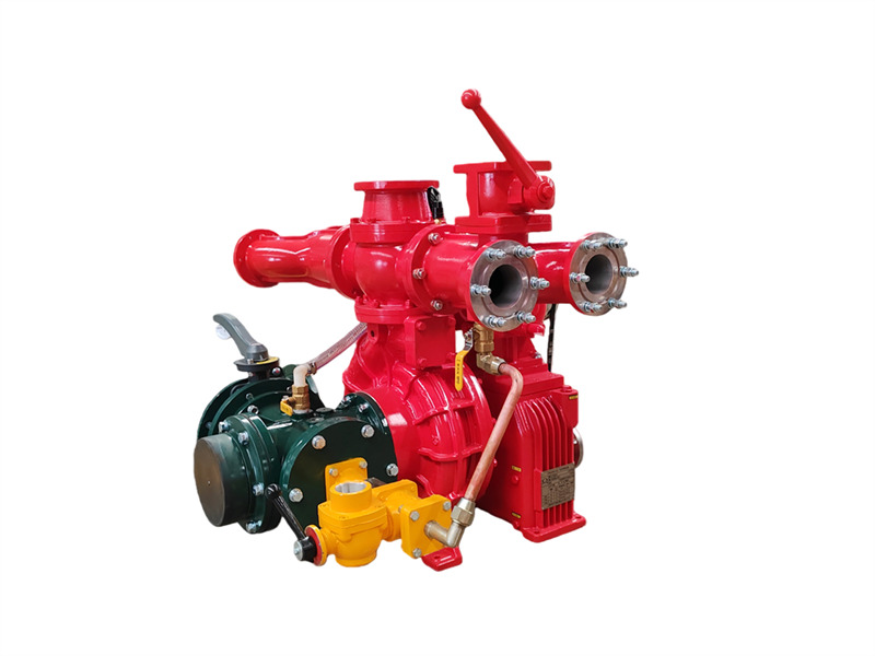
Ang CB10/60-RS na pumpang panlaban sa sunog na nakakabit sa trakay binubuo ng isang yugto na centrifugal pump na mababa ang presyon, isang double-piston vacuum pump, isang awtomatikong aparato ng electromagnetic clutch na awtomatikong naghihiwalay, isang speed increaser, isang pipeline ng labasan at shut-off valve, at isang pipeline ng pasukan. ♦ Pangunahing Estruktura at Gampanin (1) Isang yugto na centrifugal pump na mababa ang presyon:Binubuo ng takip ng pump, katawan ng pump, impeller ng unang yugto, at baras ng pump, nagbibigay ito ng itinakdang presyon at itinakdang daloy. (2) Speed increaser: Ang speed increaser ng CB10/60-RS na pumpang panlaban sa sunog na nakakabit sa sasakyan ay may karaniwang ratio ng pagpapabilis na 1.440. (3) Double-piston vacuum pump: Pangunahing binubuo ng piston, katawan ng pump, baras ng pump, at eccentric wheel. Ang eccentric wheel ay nilagyan ng piston guide rod at steel sleeve ng katawan ng pump. Ang mga balbula ng pasukan at labasan ay nakakabit sa magkabilang dulo ng piston pump. Kapag kumabit ang electromagnetic clutch, magsisimulang gumana ang piston pump. Habang gumagana, ang galaw ng eccentric wheel ay nagiging sanhi ng pag-urong at pag-usad ng piston, unti-unting inilalabas ang hangin mula sa pump at pipeline, kaya napapabuti ang kalidad ng hangin. Lumilikha ng vacuum sa loob ng lukab upang makamit ang layunin ng pagpasok ng tubig. 1. Shut-off valve ng labasan (4 na piraso); 2. Kaliwa at kanang tubo ng labasan ng tubig; 3. Konektor ng pabalik na tubig para sa pagpapalamig ng gearbox; 4. Konektor ng pressure gauge; 5. Check valve ng labasan; 6. Flange ng water cannon; 7. Water pressure switch; 8. Konektor ng pabalik na tubig ng presyon para sa pagpapalamig ng PTO; 9. Flange ng likurang tangke ng tubig; 10. Ball valve ng likurang tangke ng tubig; 11. Gearbox; 12. Electromagnetic clutch at mga kable; 13. Piston priming pump; 14. Konektor ng vacuum gauge; 15. Konektor ng vacuum priming; 16. Interface ng tubo ng pasukan; 17. Inlet four-way pipe; 18. Balbula ng alisan ng tubig ng water pump; 19. Tubo ng pabalik na tubig ng presyon para sa pagpapalamig ng gearbox; 20. Tubo ng pasok na tubig ng presyon para sa pagpapalamig ng gearbox; 21. Balbula ng antas ng lubricating oil ng gearbox; 22. Coupling flange; 23. Drive belt; 24. May sinulid na konektor ng pressure water ng foam proportioner (hindi magagamit sa mga tanker ng tubig); 25. Interface ng foam proportioner; 26. Konektor ng palabas na tubig ng presyon para sa pagpapalamig ng PTO; 27. CB10/60 na pumpang panlaban sa sunog ng sasakyan; 28. Konektor ng palabas na tubig ng presyon para sa pagpapalamig ng gearbox; 29. Likurang inlet butterfly valve (4) Pipeline ng labasan ng tubig na mababang presyon at balbula ng pagsasara: Binubuo ng check valve ng labasan ng tubig na mababang presyon, kaliwa at kanang tubo ng labasan ng tubig, apat na tubo ng labasan ng tubig, at apat na balbula ng pagsasara ng labasan ng tubig. (5) Pipeline ng pasukan ng tubig na ...
Mga detalye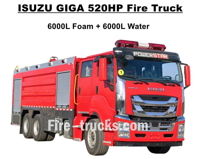
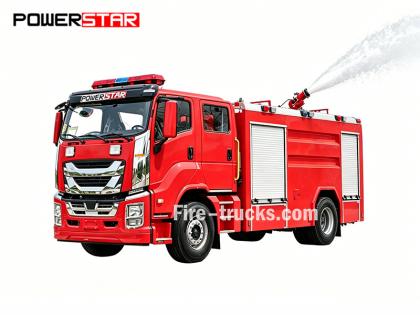
Nangungunang kalidad Mga trak panlaban sa sunog na ISUZU GIGA i-export sa Kanlurang Aprika Burkina Faso, na idinisenyo batay sa ISUZU GIGA VC66 heavy duty 6x4 chassis ng trak, gumagamit ng bagong cabin ng GIGA VC66, karaniwang upuang may air suspension at AC para sa komportableng pagmamaneho. Ang trak ay nilagyan ng diesel engine na gumagamit ng teknolohiyang Hapon ng ISUZU, modelong 6WG1-TCG62, 520HP at maaaring umabot sa 15681cc ang emisyon, ipinares sa FAST 12-bilis na manual gearbox, napakababang konsumo ng gasolina, karaniwang gulong sa harap na 385/80R22.5 at sa likuran na 315/80R22.5, kabuuang 10+1 na yunit. Kasama sa mga kit ng itaas na bahagi ang 6000L tangke ng tubig at 6000L tangke ng bula, lahat ay gawa sa materyal na hindi kinakalawang na asero #304, matibay para sa mahabang serbisyo. Ipinares sa naka-customize na napakalakas na CB10/140 fire pump na may mahusay na daloy na 140L/s, at may dobleng fire pump sa ibabaw ng kit ng tangke, na may modelong PL8/64 at mahusay na daloy na 64L/s. Isuzu GIGA 520HP makinang panlaban sa sunog na may lahat ng kinakailangang kagamitan sa paglaban sa sunog, na isang mainam na makinang panlaban sa sunog para sa pagpuksa ng apoy at pagsagip ng mga tao, at malawakang ginagamit sa merkado ng Burkina Faso. ISUZU GIGA 520HP 14,000L Foam Tank Fire Truck Pabrika ng CS TRUCKS ay isang propesyonal na tagagawa sa larangan ng mga trak,ginagarantiya ang lahat ng produkto na Bago at Mataas ang Kalidad. Mga Tampok ng ISUZU Fire Truck: Pangalan ISUZU GIGA 12000L foam pumper fire engine Cabin GIGA VC66 Makina 6WG1-TCG62 na may 520HP at 15681cc na emisyon Transmisyon FAST 12-bilis Wheelbase 4600+1370mm Gulong Harap: 385/80R22.5 (2 piraso) Likod: 315/80R22.5 (8 piraso) Tangke 6000L foam tanker (Hindi kinakalawang na asero #304) 6000L water tanker (Hindi kinakalawang na asero #304) Bomba panlaban sa sunog CB10/140 na may daloy na 140L/s Fire Monitor Harap: PL8/64 na may daloy na 64L/s Likod: PL8/64 na may daloy na 64L/s Kagamitan Kumpletong set ng kagamitan sa paglaban sa sunog ayon sa pagpapasadya Paano Patakbuhin ang ISUZU Foam Tank Fire Engine: .
Mga detalye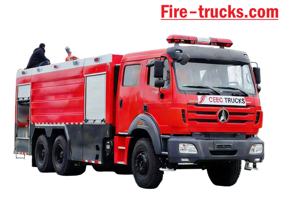
Beiben Trak ng Bumbero batay sa uri II Beiben 2638 modelo 6*4 Left Hand Drive chassis, katawan Ang kapasidad ay maaaring hanggang 12,000 Litro, kabilang ang 10,000 Litro na tangke ng tubig at 2,000 Litro na tangke ng foam, Pagsagip sa sunog ng Beiben 2638 trak nilagyan ng XIONGZHEN CB10/60 fire pump at PL8/48 fire monitor, napaka-kombenyente para sa pang-araw-araw na gamit. Pangunahing ginagamit para sa mga proyektong pang-apula ng sunog sa anumang lugar na nangangailangan. Ang sasakyang dinisenyo upang lubos na umasa sa mga bentahe ng orihinal na tsasis ng trak na tatak Beiben, lubos na isinasaalang-alang ang kaginhawahan at pagiging maaasahan ng produkto, pati na rin ang bagong dinisenyong tsasis. Ang katawan Ang materyal ay internasyonal na pamantayang carbon steel na may anti-corrosion painting at hindi kinakalawang na asero, na ay maaaring maging epektibo upang maiwasan ang kalawang at magamit nang matagal. Ang Beiben 6x4 Fire Truck na may kasamang Sandwich PTO, fire pump, fire monitor, crew room, at hose. kahon, silid ng bomba, tanker ng tuyong pulbos at sistema ng nitroheno, na itinugma sa hose reel ng tubo, Ingles version control box, tubo ng papasok at palabas, hagdan sa pag-akyat sa likuran, lampara sa itaas na unan, at lahat ng kinakailangang kagamitan sa pag-apula ng bumbero. Pasadyang double-row cabin na may 2+4 na upuan, magandang pakiramdam sa pagmamaneho. Samakatuwid, ang Ang sasakyan ay isang mainam na Truck ng Bumbero pangunahin na para sa mga proyektong pang-apula ng sunog. [kung gte mso 9]> Normal 0 7.8 磅 0 2 false false false EN-US ZH-CN X-NONE (trueWeb Name)="NormalException" Locked="false" SemiHidden="true" UnhideWhenUsed="true" Name="HTML Acronym"/> /* Style Definition */ table.MsoNormalTable {mso-style-name:普通表格; mso-tstyle-rowband-size:0; mso-tstyle-colband-size:0; mso-style-noshow:yes; mso-style-priority:99; mso-style-parent:""; mso-padding-alt:0cm 5.4pt 0cm 5.4pt; mso-para-margin:0cm; mso-pagination:balo-ulila; laki ng font:10.0pt; font-family:"Times New Roman",serif; mso-fareast-language:EN-US;}
Mga detalye
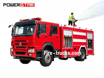
Ang kliyente ng Africa Mauritania ay bumili ng kabuuang 4 na yunit Sinotruk HOWO pumper fire engine Mula sa POWERSTAR TRUCKS at ginagamit sa kabisera ng Nouakchott. Ang trak ng bumbero ay maaari ding tawaging fire engine at fire pumper, na isang sasakyan na idinisenyo at ginawa upang matugunan ang mga pangangailangan ng maraming proyekto sa pamatay-sunog at pagsagip ng mga tao sa buong mundo. Na-customize na double cabin row para sa mga karwahe ng mga bumbero, iba't ibang kagamitan at kagamitan sa pamatay-sunog para sa pag-apula ng sunog, pagsagip sa sunog, atbp. Upang matiyak na mas mahusay na gumagana ang mga trak ng pamatay-sunog ng HOWO, ginawa naming customized ang trak na may mga hagdan na gawa sa Aluminum alloy, water foam at dry powder fire agent at storage tanker, mahusay na fire pump CB10/60 model na tugma sa PL8/48 fire monitor, at mahusay na distansya ng pag-jetting na mahigit 70m, hose reel ng pamatay-sunog na may baril para sa malayuang pamatay-sunog, breathing apparatus na may maskara, proteksiyon na damit, mga kagamitan sa pagsagip, first-aid kit, atbp. Lahat ng serbisyo para sa mga trak ng bumbero ng HOWO para sa mahusay at maaasahang pagtatrabaho. Upang matiyak na mas madali at mahusay na magagamit ng mga kliyente ng Mauritania ang HOWO fire engine, lahat ng trak ay tugma sa kumpletong set ng katalogo ng bersyong Ingles para sa serbisyo, kabilang ang User's Manual para sa gabay sa operasyon, Truck Manual at Spare Parts Manual para sa paggamit at pagpapanatili. Trak ng Bumbero ng SINOTRUK HOWO 14,000L na Pulbos na Pampagana Pabrika ng POWERSTAR ay propesyonal na tagagawa sa larangan ng trak, garantisado ang lahat ng produktong bago at de-kalidad. » Ⅰ. Mga Kalamangan ng Trak ng Bumbero ng HOWO: ★ 247KW / 336HP na makapangyarihang diesel engine na WEICHAI, 100,000 Km nang walang problema. ★ SINOTRUK HOWO klasikong HW76 cabin, disenyong Europeo ★ Naka-mount na CB10/60 fire pump, 60L/s flow rate, sobrang maaasahan ★ PL8/48 water fire cannon na naka-mount sa itaas, matibay na serbisyo ★ 500L na tuyong pulbos na may bote ng Nitrogen, na may mga balbula ng kontrol ng hangin ★ Pinagsamang sistema ng kontrol para sa foam at powder, na may panel sa likuran » Ika-2 . Guhit ng Howo Rescue Fire Engine: [kung gte mso 9]> Normal 0 7.8 磅 0 2 false false false EN-US ZH-CN AR-SA (trueWeb Name)="NormalException" Locked="false" SemiHidden="true" UnhideWhenUsed="true" Name="HTML Acronym"/> /* Style Definitions */ table.MsoNormalTable {mso-style-name:普通表格; mso-tstyle-rowband-size:0; mso-tstyle-colband-size:0; mso-style-noshow:yes; mso-style-priority:99; mso-style-parent:""; mso-padding-alt:0cm 5.4pt 0cm 5.4pt; mso-para-margin:0cm; mso-pagination:widow-orphan; font-size:10.0pt; font-family:"Calibri",sans-serif; mso-bidi-font-family:"Times New Roman";} To guarantee Mauritania Nouakchott clients purchased satisfy HOWO 6x4 Water & Foam & Powder Fire Truck, so we POWERSTAR Engineer Department do design the truck firstly, then start for production. Howo fir...
Mga detalye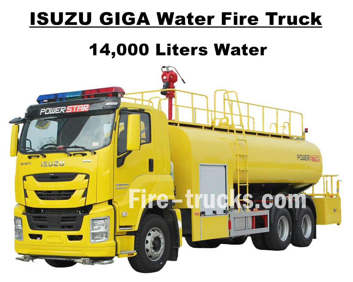
Ang customer ng South American na si Mr Joseph mula sa Hondura, na bumili ng 1 unit Isuzu GIGA VC66 14000L 3700gallons water fire fighting truck mula sa POWERSTAR TRUCKS, na idinisenyo batay sa Japanese ISUZU GIGA 6x4 heavy duty truck chassis, nilagyan ng 6UZ1-TCG60 model diesel engine na may horse power na 280kw / 380HP, na isang 6-cylinder, 4-stroke, water-cooled, turbocharged at intercooled na makina, mahusay na gumaganang international shift na may FAST na tugma 192 ml, manu-manong shift 98ml. gearbox, 12 shift pasulong at 2 shift paatras, mahusay na bawasan ang pagkonsumo ng gasolina, ganap na naka-install ng 13 unit na bakal na gulong na may modelong 12R22.5 na modelo, kabilang ang isang ekstrang gulong, napaka-angkop para sa maraming uri ng kondisyon ng kalsada at angkop para sa pag-akyat sa bundok. Ang wheelbase ay maaaring maramihang opsyonal na may 4600+1370mm, angkop at maginhawang dinisenyong serbisyo para sa proyektong pamatay ng sunog para sa maraming lugar. Ang Isuzu GIGA 3700 gallons na water tanker fire engine ay ganap na umaasa sa Japanese technology na ISUZU truck chassis, orihinal na GIGA VC66 cabinet na nilagyan ng A/C na may heating at cooling function para sa komportableng pagmamaneho. At ang truck na naka-mount na may full stainless steel SS304 material water tanker body, na may mahusay na volume na 14000Liters, katumbas ng 3700gallons, nilagyan ng isang Chinese brand na CB10/60 fire pump at PS8/50 fire monitor sa tuktok ng tanker body, full set na fire fighting rescue equipment, at customized na lemon yellow na pagpipinta para sa buong trucking at ideal na sasakyan sa kalye para sa paggawa ng sunog sa Hondurushing project. Itinugma din ang trak sa buong hanay ng English version catalog para sa serbisyo, kasama ang User's Manual para sa gabay sa pagpapatakbo, Truck Manual para sa GIGA truck na paggamit, Spare Parts Manual para sa maintenance. Isuzu GIGA 14,000L Water Pumper Fire Fighting truck Pabrika ng POWERSTAR ay propesyonal na tagagawa sa lugar ng trak, ginagarantiyahan ang lahat ng mga produkto Brand-New at High-Quality. » Ⅰ. Mga Bentahe ng Isuzu Water Fire Truck: ★ 280KW / 380HP malakas na 6WG1 diesel engine, 100,000 Km na walang problema. ★ ISUZU VC66 bagong GIGA cabin, European na disenyo ★ Naka-mount na CB10/60 fire pump, 60L/s flow rate, sobrang maaasahan ★ Top mounted PS8/50 water fire cannon, matibay na serbisyo ★ Integrated control system, na may panel sa gilid ★ Customized lemon dilaw na pagpipinta, nagniningning at maganda CB10/60 bomba ng sunog Modelo : CB10/60 Presyon : 1.0Mpa Max. Presyon sa Paggawa : 1.232Mpa Rate ng Daloy : 60L/s sa 1.0Mpa, bilis 3286±50r/min, kapangyarihan 102kW, lalim ng pagsipsip 3m 42L/s sa 1.3Mpa, bilis 3519±50r/min, kapangyarihan 106kW, lalim ng pagsipsip 3m 30L/s sa 1.0Mpa, bilis 3120±50r/min, kapangyarihan 73kW, lalim ng pagsipsip 7m Ratio ng Bilis : 1:1.44 PS8/50 Fire Monitor Modelo : PS8/50 Presyon : 0.8Mpa Saklaw ng Paggawa : Tubig ≥ 65 m Patayong Pag-ikot : -45° ~ +70° Paha...
Mga detalye
Gumagawa ang Powerstar Trucks ng Mga Custom na Sasakyan para sa Pagtugon sa Emergency at Mga Fire Truck Sa loob ng ilang taon, itinatag ng Powerstar trucks Emergency Response ang legacy nito bilang nangungunang full-line na tagagawa ng custom fire apparatus na may kadalubhasaan sa foam water fire trucks at rescue fire sasakyan . Binubuo ang mga pamana na pinagkakatiwalaan ng mga bumbero, ang mga Powerstar truck ay naghahatid ng nababaluktot, estratehiko, at espesyal na mga solusyon upang matugunan ang bawat natatanging pangangailangan ng departamento ng bumbero, na inuuna ang mga unang tumugon. 120 units Rescue fire truck para ihatid 65 units Rescue Fire Truck export sa Uganda Police Mga trak ng Bumbero sa Tubig Foam fire fighting sasakyan Pangunahing inuri ang mga trak ng bumbero sa apat na kategorya ayon sa kanilang paggana: mga trak na panlaban sa sunog, mga trak na panghimpapawid sa himpapawid, mga trak ng bumbero na may espesyal na layunin, at mga trak ng bumbero ng suportang logistik. 01, Mga trak na lumalaban sa sunog ay ang pangunahing puwersa para sa direktang pag-apula ng apoy, kabilang ang: * **Mga Water Tank Fire Truck:** Nilagyan ng sarili nilang tangke ng tubig at pump, na angkop para sa pagpuksa ng mga pangkalahatang sunog. * **Foam Fire Truck:** Partikular na idinisenyo para sa pag-apula ng apoy na kinasasangkutan ng mga nasusunog na likido gaya ng langis. * **Mga Dry Powder Fire Truck:** Angkop para sa pamatay ng gas at mga sunog sa kuryente. * **Mga Carbon Dioxide Fire Truck:** Ginagamit upang protektahan ang mahahalagang kagamitan at mga instrumentong katumpakan. * **Foam-Dry Powder Combined Use Trucks:** Maaaring gamitin ang parehong extinguishing agent nang sabay-sabay, na may malawak na hanay ng mga application. 02, Aerial Ladder Fire Truck ay ginagamit para sa pagsagip at paglaban sa sunog sa mga matataas na gusali, pangunahin kasama ang: * **Ladder Fire Truck:** Nilagyan ng teleskopikong hagdan, na may kakayahang magligtas ng mga tao at mapatay ang apoy sa taas. * **Aerial Spray Fire Truck:** Gumamit ng malayuang kinokontrol na boom upang mag-spray ng mga ahente ng pamatay sa malalayong distansya. * **Aerial Platform Fire Trucks:** Magbigay ng hydraulic lifting platform para sa pagsagip at paglaban sa sunog. Application ng trak ng bumbero 03, Ang mga dalubhasang trak ng bumbero ay may pananagutan para sa mga partikular na gawain, tulad ng: * **Rescue and Disaster Relief Fire Trucks:** Nilagyan ng demolition tools at lifting equipment, na ginagamit para sa aksidenteng rescue. * **Pag-iilaw ng Mga Fire Truck:** Magbigay ng mataas na intensidad na ilaw para sa mga operasyon sa pagsagip sa gabi. * **Smoke Extraction Fire Truck:** Ginagamit para sa mga operasyon ng pagbunot ng usok sa mga sunog sa ilalim ng lupa. 04, **Logistical Support Fire Trucks:** Pangunahing nagbibigay ng logistical support sa pinangyarihan ng sunog, gaya ng: * **Mga Fire Truck ng Water Supply:** Magbigay ng tuluy-tuloy na supply ng tubig sa mga fire truc...
Mga detalye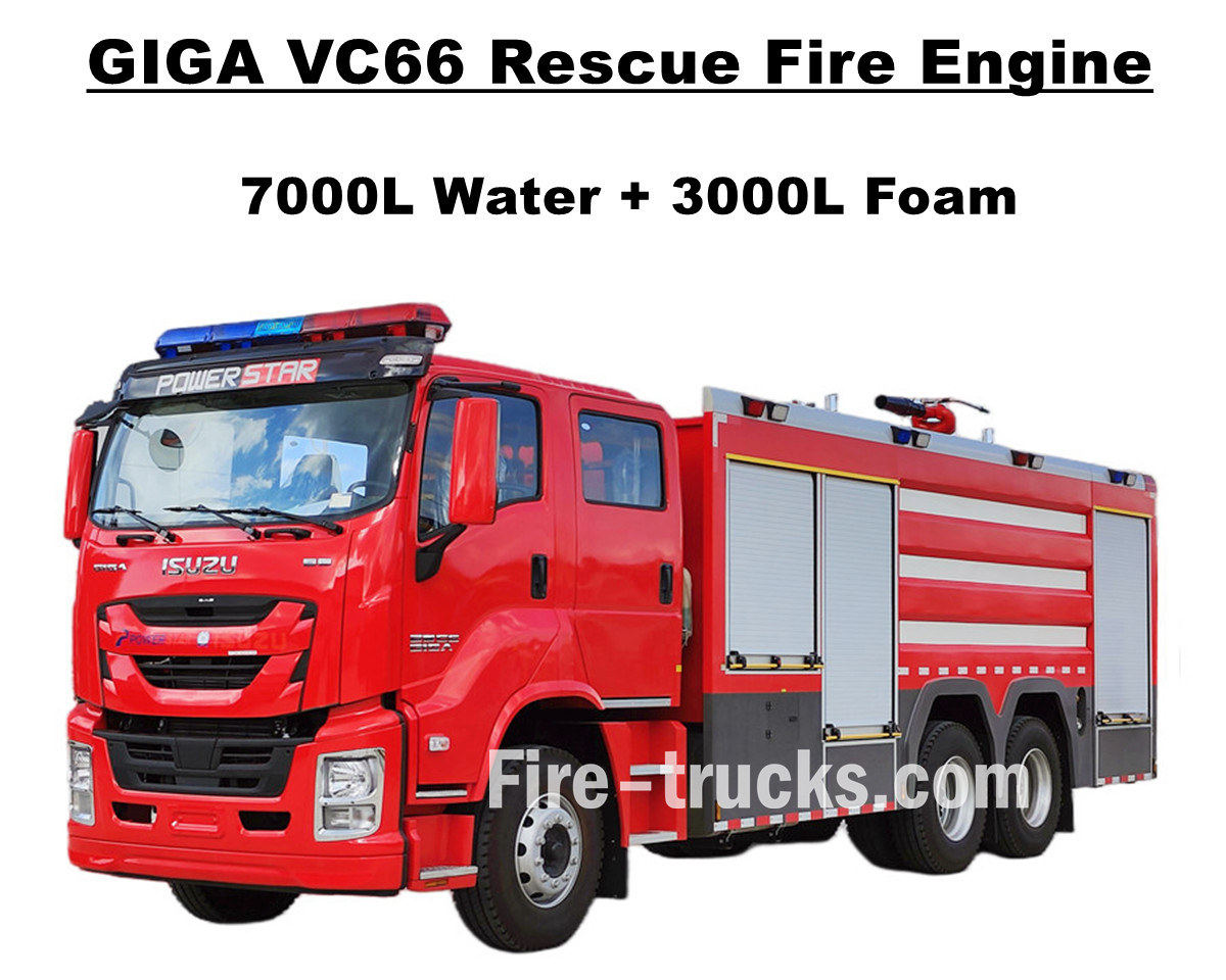
Philippines Manila mga customer na binili Isuzu GIGA VC66 heavy duty fire fighting truck mula sa POWERSTAR TRUCKS, na nilagyan ng Japanese ISUZU diesel engine na 6WG1-TCG61 na may horse power na 338kw / 460HP, na isang 6-cylinder, 4-stroke, water-cooled, turbocharged at intercooled na makina, na dinisenyong displacement ng 15681cc standard, na tumutugma sa pagtatrabaho sa international standard na 2 shift na FAST 12 12 shift manual gearbox, pasulong at manu-manong paglipat. pagkonsumo ng gasolina, ganap na naka-install ng 13 mga yunit ng tubeless na gulong na may modelong 315/80R22.5 na modelo, kabilang ang isang ekstrang gulong, na angkop para sa maraming uri ng kondisyon ng kalsada. at serbisyo para sa fire extinguishing project para sa maraming lugar. Ganap na umasa sa orihinal na ISUZU GIGA VC66 truck chassis, baguhin ang GIGA double-row cab na may 2+1 normal na upuan sa harap at 4 na upuan sa likuran ng SCBA, sa cabin na nilagyan ng A/C na may heating at cooling function para sa komportableng pagmamaneho. At ang truck na naka-mount na may full stainless steel SS304 material tanker body, nilagyan ng Top one Chinese brand na XIONGZHEN CB10/60 fire pump sa rear pump room, tumugma sa pagtatrabaho sa WESTER PL8/48 fire monitor sa tuktok ng tanker body, full sets fire fighting rescue equipment, lahat ay ginagawang perpektong sasakyan ang trak para sa fire extinguishing project sa kalye at komunidad ng Maynila. Itinugma din ang trak sa buong hanay ng English version catalog para sa serbisyo, kasama ang User's Manual para sa gabay sa pagpapatakbo, Truck Manual para sa GIGA truck na paggamit, Spare Parts Manual para sa maintenance. Isuzu 7,000L Water 3,000L Foam Fire Fighting truck Pabrika ng POWERSTAR ay propesyonal na tagagawa sa lugar ng trak, ginagarantiyahan ang lahat ng mga produkto Brand-New at High-Quality. » Ⅰ. Isuzu 6WG1 Fire Truck Pangunahing Tampok : ★ 338KW / 460HP malakas na 6WG1 diesel engine, 100,000 Km na walang problema. ★ ISUZU VC66 bagong GIGA cabin, European na disenyo ★ Double row cabin, na may 4 na upuan sa likod ng SCBA ★ Naka-mount na CB10/60-XZ fire pump, 60L/s flow rate, sobrang maaasahan ★ Top mounted PL8/48 foam fire cannon, matibay na serbisyo ★ Integrated control system, na may panel sa likuran CB10/60-XZ bomba ng sunog Modelo : CB10/60-XZ Presyon : 1.0Mpa Max. Presyon sa Paggawa : 1.232Mpa Rate ng Daloy : 60L/s sa 1.0Mpa, bilis 3286±50r/min, kapangyarihan 102kW, lalim ng pagsipsip 3m 42L/s sa 1.3Mpa, bilis 3519±50r/min, kapangyarihan 106kW, lalim ng pagsipsip 3m 30L/s sa 1.0Mpa, bilis 3120±50r/min, kapangyarihan 73kW, lalim ng pagsipsip 7m Ratio ng Bilis : 1:1.44 PL8/48 Fire Monitor Modelo : PL8/48 Presyon : 0.8Mpa Saklaw ng Paggawa : Foam ≥ 70m at Tubig ≥ 60m Patayong Pag-ikot : -45° ~ +70° Pahalang na Pag-ikot : 0° ~ 360° Rate ng Daloy : 48 L/s » Ⅱ . Isuzu Fire Rescue Truck teknikal na pagguhit: ISUZU GIGA VC66 fire engine na may tubig at foam tanker, na itinugma sa XIONGZHEN CB10/60 fire monitor at Wester PL8/48 fir...
Mga detalye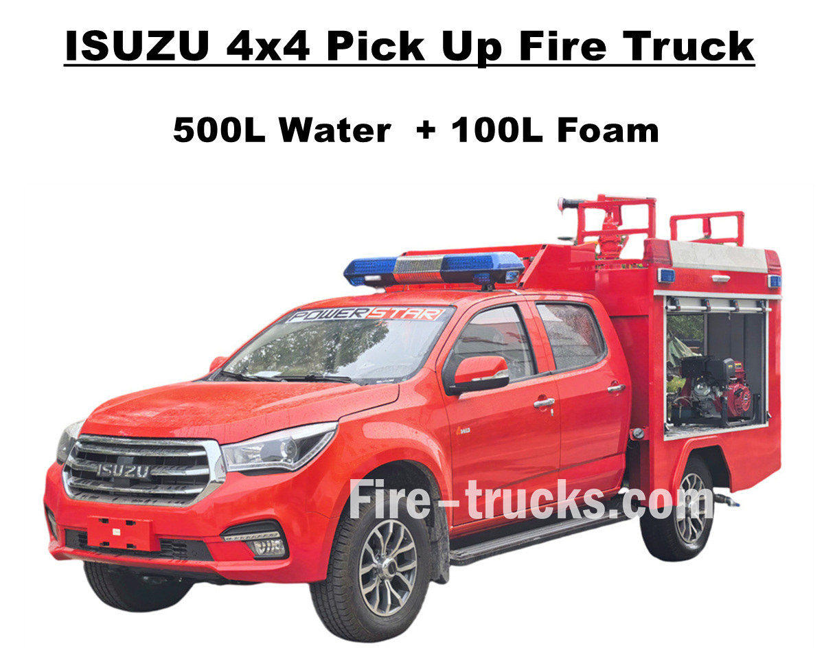
Pagbebenta ng pabrika ISUZU 4x4 offroad pick up fire truck gamitin ang ISUZU TAGA sa lahat ng wheel drive chassis, isinasama ang isang mahusay na sistema ng kapangyarihan upang hamunin ang lahat ng uri ng mahirap na mga kalsada. Ang Isuzu pickup fire rescue truck ay nilagyan ng full stainless steel SS304 material tanker assembly, kabilang ang 500 liters water tank at 100 liters foam tank, at isang propesyonal na independent fire pump na JBQ4.5/9 na ikakabit sa rear pump room, na may mahabang spray distance at opsyonal na control panel language. Nagbibigay din ito ng iba't ibang opsyonal na configuration para matugunan ang iba't ibang pangangailangan, at naka-mount sa itaas na may PS20 fire monitor para sa water jetting. Ang ISUZU Pickup 143HP fire pumper truck na ito ay nagbibigay ng matibay na garantiya para sa kaligtasan ng sunog at nagpapakita ng mahusay na performance at flexibility. Ang orihinal na double-row na cab ng Isuzu fire fighting truck ay nagbibigay ng sapat na espasyo at kalidad upang maikarga ang mga kagamitan sa paglaban sa sunog at mapanatili ang mahusay na pagganap sa pagmamaneho. Ang taksi ay maaaring tumanggap ng 5 bumbero at nilagyan ng air conditioning upang matiyak na ang driver ay mananatiling komportable sa anumang kondisyon ng panahon. At ginagarantiyahan ng lahat ang ISUZU 600L foam fire engine na isang mainam na serbisyo ng sasakyan sa pagliligtas ng sunog para sa merkado ng Albania. At sa ibaba ng User Manual ay nilagyan para sa kaligtasan ng operasyon at pagtatrabaho. » Ⅰ. Mga Pangunahing Tampok ng Isuzu Pick Up Fire Truck : ★ 105KW / 143HP malakas na 4KH1 engine, 100,000 Km na walang problema. ★ ISUZU TAGA bagong pickup cabin, European na disenyo ★ Orihinal na double cabin, na angkop para sa 5 bumbero ★ Independent JBQ4.5/9 fire pump, sobrang maaasahan ★ Top mount PS8/20 fire cannon, matibay na serbisyo » Ⅱ. Pangkalahatang-ideya ng pick up fire tender: Ang ISUZU 4x4 offroad AWD Water Foam Fire Fighting Truck ay isang all terrain fire rescue truck, na nagseserbisyo para sa maraming aera, kabilang ang komunidad, kagubatan, pabrika, atbp. Dahil sa kakayahan nito sa offroad at makitid na hitsura, ang Isuzu Pickup fire engine na ito ay maaaring magtagumpay sa maraming misyon na natapos. At para gawing mas angkop ang aming mga fire truck, nasa ibaba ang mga opsyon para sa iba't ibang kliyente. ----- Materyal ng tanke : Carbon steel, hindi kinakalawang na asero, aluminyo haluang metal, PP materyal ----- Fire Pump : Batay sa tanker body at jetting distance, opsyonal na American Darley tatak ----- Opsyonal: Pipeline, hose reel, aluminum ladder, Pinagsanib na modelo (Chinese, European, American type) » Ⅲ. Kaakit-akit na Hitsura: Ang ISUZU 4x4 AWD pick up fire truck ay makapangyarihan at tumutugon, mabilis na makakarating sa pinangyarihan ng sunog, at madaling makadaan sa kumplikadong lupain. Ang tuktok na kanyon ng apoy ay may mahabang hanay at isang malaking rate ng daloy, at ang mas mahabang 50m fire fighting hose reel na ...
Mga detalye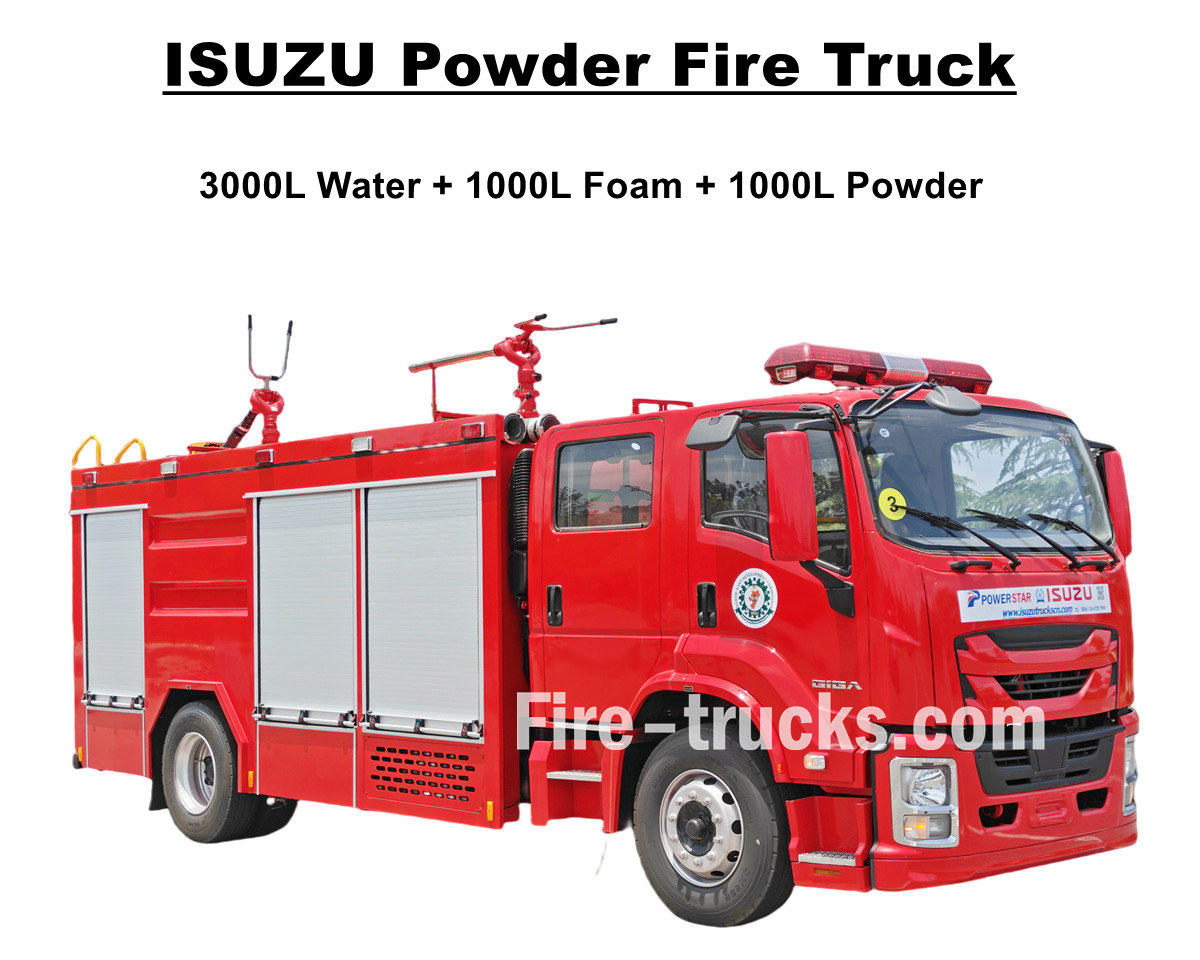
Bagong dinisenyo at ginawa ISUZU GIGA 4X water foam dry powder fire fighting truck ay isang high performance na ISUZU fire engine na nag-e-export sa Nigeria Lagos, na nilagyan ng 4HK1-TCG60 diesel engine na may 150KW/205HP at emission 5193cc, tumugma sa pagtatrabaho sa MLD 6 shift manual transmission gearbox, 6 forward at 1 reverse, mahusay na power output at mas mababang fuel consumption, tinitiyak din ang mas mabilis na pagtugon at stable na pagmamaneho. Isuzu 5000L fire engine na nilagyan ng ganap na 5000L tanker body kit, kabilang ang 3000L water tanker, 1000L foam tanker at 1000L dry powder tanker, lahat ng tanker ay gumagamit ng stainless steel na SS304 na materyal, square shape na disenyo na may baffle sa loob, top matched sa DN500 manhole cover at lock para sa kaligtasan. Ang mga Isuzu powder fire pumper truck ay nilagyan ng CB10/40 fire pump, na may mahusay na flow rate na 40L/s, na tumutugma sa pagtatrabaho sa PL8/32 water foam fire monitor na may mahusay na halo-halong water foam flow rate na 32L/s, na nagtatrabaho sa maraming kagamitan sa pagsagip sa sunog upang gawing perpektong sasakyan para sa pagliligtas ng sunog ng mga tao, Lagos at bansang Nigeria. Itinugma din ang trak sa Dry Powder Tanker na may modelong R25-006 series, dinisenyo ang pressure na 1.55Mpa at dinisenyo ang volume na 1000lits, na nilagyan din ng mahusay na mga bote ng nitrogen para sa paggamit. At para magarantiyahan ang operasyon ng mga fire truck ng ISUZU at ang pagganap ng higit na kahusayan, sa ibaba ng nakalakip na manual ay para sa mga kagamitan para sa gabay ng customer ng Nigeria. ♦ ISUZU GIGA Dry Powder Fire Fighting Truck ♦ POWERSTAR ISUZU Dry Powder Fire Truck Manual export Nigeria ISUZU fire fighting trucks control panel Detalyadong bahagi ng ISUZU fire rescue truck » Ⅰ. Mga Pangunahing Tampok ng Isuzu Fire Truck: ★ 205 Hp malakas na 4HK1 engine, 100,000 Km walang problema. ★ ISUZU GIGA bagong modelong 4X cabin, European na disenyo ★ ISUZU technology axle, lubhang angkop para sa AFRICA. ★ China sikat CB10/40 pump, sobrang maaasahan ★ Top design PL8/32 fire cannon, matibay ★ Dry powder assembly, katugmang Nitrogen bottles » Ⅱ.Tagagawa ng ISUZU Fire Tender: Ang ISUZU GIGA Water Foam Dry Powder Fire Fighting Truck ay isang fully functional na medium-sized na main battle fire truck, na nagsasama ng malakas na mobility, sapat na extinguishing agent reserves, at magkakaibang kakayahan sa labanan. Sa mga tuntunin ng kapangyarihan, nagtatampok ito ng Weichai engine na ipinares sa isang Sinotruk transmission, na nagbibigay ng malakas na kapangyarihan at mahusay na transmission. ----- Materyal ng tanke : Carbon steel, hindi kinakalawang na asero, aluminyo haluang metal, PP materyal ----- Fire Pump : Batay sa tanker body at jetting distance, opsyonal na American Darley tatak ----- Opsyonal: Pipeline, hose reel, aluminum ladder, Pinagsanib na modelo (Chinese, European, American type) Isuzu rescue fire trucks para sa produksyon ISUZU 205HP fire fighting truck para ...
Mga detalye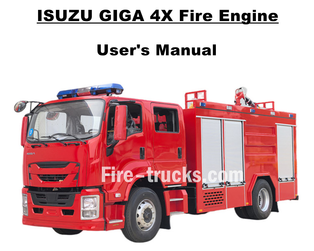
Ang mga customer ng Moldova ay bumili ng 6 na yunit Isuzu GIGA 4X airport fire rescue truck mula sa POWERSTAR TRUCKS, at serbisyo para sa fire extinguishing project para sa maraming lugar. Ganap na umasa sa orihinal na ISUZU GIGA 4X truck chassis, baguhin ang GIGA 4X double-row cab na may harap na 2+1 normal na upuan at likurang 4 SCBA na upuan, sa cabin na nilagyan ng A/C na may heating at cooling function para sa komportableng pagmamaneho. Nilagyan ng Japanese ISUZU diesel engine na 4HK1-TCG60 na may horse power na 151kw / 205HP, na isang four-cylinder, four-stroke, water-cooled, turbocharged at intercooled na makina, dinisenyong displacement ng 5193cc standard, tumugma sa pagtatrabaho sa ISUZU MLD 6 na shift na manu-manong paglipat ng gearbox, 1 shift na manu-manong paglipat ng pasulong, at 1 shift na manu-manong paglipat ng pasulong na gasolina. ganap na naka-install na 7 unit na tubeless na gulong na may modelong 295/80R22.5 na modelo, napaka-angkop para sa maraming uri ng kondisyon ng kalsada. Isuzu 5,000L Water 1,000L Foam Fire truck Pabrika ng POWERSTAR ay propesyonal na tagagawa sa lugar ng trak, ginagarantiyahan ang lahat ng mga produkto Brand-New at High-Quality. » Ⅰ . Mga Application sa Paglaban sa Sunog: Ang ISUZU GIGA 4X na bagong idinisenyong 205HP fire fighting truck na may kumpletong set ng fire fighting equipment at mga people rescue tool, na may mahusay na water at foam jetting distance at flow rate, at angkop para sa maramihang fire extinguishing work sa lungsod, pabrika, komunidad, atbp. Mga detalyadong advanced na feature tulad ng nasa ibaba: 1. ISUZU GIGA 4X Truck: Japanese ISUZU 4HK1-TCG60 model na may 151KW / 205HP diesel engine 2. SS304 Material Tanker: Customized na 5000L water tanker at 1000L foam tanker, lahat ay nakabatay sa stainless steel SS304 3. CB10/40 Fire Pump: Naka-mount sa likuran, na may independiyenteng silid, magagamit na pump in at pump out function CB10/40 bomba ng sunog Modelo : CB10/40 Presyon : 1.0Mpa Max. Presyon sa Paggawa : 1.38Mpa Rate ng Daloy : 40L/s sa 1.0Mpa, bilis 3330±50r/min, kapangyarihan 60kW, lalim ng pagsipsip 3m 28L/s sa 1.3Mpa, bilis 3540±50r/min, kapangyarihan 59kW, lalim ng pagsipsip 3m 20L/s sa 1.0Mpa, bilis 3335±50r/min, kapangyarihan 42kW, lalim ng pagsipsip 7m Ratio ng Bilis : 1:1.542 4. PL8/36 Fire Monitor: Top mounted, manual operaiton model na may available na jetting distance na mahigit 55m, mahusay at matibay PL8/36 Fire Monitor Modelo : PL8/36 Presyon : 0.8Mpa Saklaw ng Paggawa : Foam ≥ 60m at Tubig ≥ 48m Patayong Pag-ikot : -45° ~ +70° Pahalang na Pag-ikot : 0° ~ 360° Rate ng Daloy : 36L/s 5. Pinagsama Kontrolin ang Device : ISUZU fire fighting trucks na nilagyan ng integrated control device sa rear pump room, maginhawa at matalino. » Ⅱ . Mga Advanced na Feature ng Fire Engine: Ang ISUZU GIGA 4X heavy duty rescue fire engine ay isang mainam na trak na panlaban sa sunog para sa pamatay ng sunog at pagliligtas ng mga tao. Na may mga advanced na tampok para sa disenyo at ma...
Mga detalye
Mangyaring magpatuloy sa pagbabasa, manatiling nakaantabay, mag-subscribe, at malugod naming hinihintay ang inyong mga komento.

 Suportado ang network ng IPv6

 Filipino
 English
 français
 Deutsch
 русский
 italiano
 español
 português
 Nederlands
 العربية
 日本語
日本語 한국의
한국의 Türkçe
 Melayu
 ไทย
ไทย Tiếng Việt
 Indonesia
  中文
中文 қазақ
қазақ မြန်မာ
 српски