Mag-iwan ng Mensahe
Kung interesado ka sa aming mga produkto at gusto mong malaman ang higit pang mga detalye, mangyaring mag-iwan ng mensahe dito, sasagutin ka namin sa lalong madaling panahon.

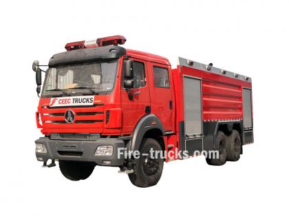
The fire truck PTO (Power Take-Off) is a power transmission device that transfers engine power to the fire pump. When the firefighter activates the PTO, mechanical power from the engine is transmitted through the transmission and PTO to the fire pump — this is the core working principle of how a fire fighting truck PTO system operates — enabling the pump to deliver high-pressure, high-flow water or foam without the need for a separate auxiliary engine.
Modern fire trucks typically use side-mounted PTO or full power PTO systems. These offer stable power output, convenient operation, and low maintenance costs, making them an essential component of the fire truck's firefighting system.
 Work")
PTO (Power Take-Off) is a critical component in the fire truck's power system. It is a gear transmission device installed between the engine and the transmission, designed to "divert" a portion of mechanical power from the vehicle's engine or transmission to the fire pump or other auxiliary equipment, without affecting the vehicle's normal driving capability.
The fire truck engine is originally responsible only for driving the wheels. However, once the fire truck arrives at the fire scene, the wheels no longer need power, while the fire pump requires power to draw and pressurize water. The PTO is the device that accomplishes this "power switch."

Power Take-Off (PTO) literally means "power output device."
On a fire truck, it refers to extracting rotational power from the engine flywheel or transmission gears through gear engagement, and delivering it to the fire pump or other auxiliary equipment.
Its name describes its function:
Engine = Power source
PTO = Power distributor
Fire pump = Power consumption end
Therefore, the PTO is the bridge connecting the "power source" and the "firefighting system."
The core reason fire trucks must be equipped with a PTO is that firefighting operations require continuous, stable, high-power output that cannot rely on the vehicle's driving state.
Main reasons:
1. Provides continuous firefighting power
The fire pump needs to run for extended periods during firefighting operations. The PTO allows the engine to continuously drive the fire pump at idle or fixed RPM, ensuring stable water pressure and flow.
2. Improves power utilization efficiency
Without a PTO, a separate auxiliary engine would be required to drive the fire pump, which would increase:
Cost
Maintenance complexity
Risk of failure
Space occupation
The PTO directly utilizes the vehicle's engine power, improving overall efficiency.
3. Supports multiple firefighting systems
Modern industrial fire trucks may include not only water pumps but also:
Foam systems
Dry powder systems
High-pressure water systems
Remote-controlled fire monitors
Without a PTO, there are only two solutions:
Install a separate engine to drive the pump → increases weight, cost, maintenance points, and occupies space
Keep the pump permanently connected to the transmission → pump stops when vehicle stops, unable to pump water on site
The PTO solves both problems at once:
| Mode | PTO Status | Power Destination | Result |
| Driving mode | Disengaged | All to wheels | Normal driving |
| Firefighting mode | Engaged | All to fire pump | Pumping while stationary |
The PTO is essentially a "power distribution and conversion system" that transforms vehicle driving power into firefighting operational power.
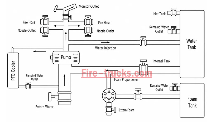
From an engineering perspective, the complete power path is:
Engine → Transmission → PTO → Drive Shaft → Fire Pump → Fire Monitor/Hose System
The PTO's working principle can be summarized in three key stages: power take-off, engagement, and transmission.
The PTO draws power from the engine. Depending on the installation position, the power take-off method differs:
| PTO Type | Installation Position | Power Source | Characteristics |
| Side-mounted PTO | Transmission side | Transmission countershaft gear | Simple structure, lower power (≤50% engine power) |
| Sandwich PTO | Between engine and transmission | Engine flywheel | Full power output, mainstream configuration |
| Split-shaft PTO | Between transmission and driveshaft | Transmission output shaft | High power, allows pumping while driving |
After the driver presses the PTO switch in the cab, the engagement mechanism activates:
| Engagement Method | Working Principle | Common On |
| Electric solenoid control | Electrical signal activates solenoid, pushing shift fork | Mainstream on modern fire trucks |
| Pneumatic control | Compressed air pushes piston, actuating fork | Large fire trucks |
| Manual cable | Mechanical cable directly pulls fork | Older vehicles |
Operation sequence:
Press PTO switch → Solenoid/cylinder actuates → Shift fork pushes sliding gear → Meshes with flywheel or transmission gear → Power connected
After the PTO output shaft begins rotating, power is transmitted through the drive shaft to the fire pump:
PTO output shaft rotates → Drive shaft → Fire pump input shaft → Pump impeller rotates → Water is pressurized and discharged
| Step | Action | Result |
|---|---|---|
| Step 1 | Engine starts, vehicle idling or driving | Engine running, PTO disengaged |
| Step 2 | Arrive at scene, driver presses PTO switch | Driving power disengaged (on some models), PTO gear activated |
| Step 3 | PTO establishes power connection with transmission | Transmission power is diverted to PTO output shaft |
| Step 4 | Drive shaft transmits power to fire pump | Fire pump begins receiving continuous mechanical power |
| Step 5 | Fire pump impeller rotates at high speed | Suction → Pressurization → Delivery to discharge lines → Firefighting |
| Step 6 | System reaches balanced RPM | Stable output, adjustable pressure, flow, and spray pattern |
The fire truck PTO system is a complete power transmission chain, with multiple components working together to transfer engine power to the fire pump. The system can be broken down into six core components:
The engine is the power source of the PTO system and the heart of the entire fire truck.
Function: Generates raw rotational power, driving the flywheel or crankshaft.
Power output: Typically 300–600 HP (depending on chassis model and configuration).
Relationship with PTO: The PTO draws power from the engine flywheel or crankshaft — it is the starting point of power.
Key characteristic: Engine RPM directly affects PTO output speed and the fire pump's water discharge capability. Fire trucks are typically equipped with high-power diesel engines, which not only drive the vehicle but also provide ample power reserve for the fire pump. After PTO engagement, the operator can control pump discharge pressure by adjusting engine RPM.
The transmission is responsible for power delivery and speed matching.
Function: Receives engine power and adjusts speed and torque through different gear combinations.
Relationship with PTO: Side-mounted PTO draws power from internal transmission gears; sandwich PTO is installed at the front of the transmission.
Key characteristic: Transmission gear position does not affect PTO output speed — PTO operates independently of gear selection.
Two power take-off positions:
Transmission side window take-off: PTO mounted on transmission side, drawing power from countershaft or intermediate shaft gears; common on medium-duty fire trucks.
Transmission rear-end take-off (sandwich): PTO installed between engine and transmission, drawing power directly from the flywheel, enabling full power output.
The PTO is the core of the entire system, responsible for "extracting" power from the engine and delivering it to the fire pump.
Function: Extracts power from the engine or transmission and converts it to the speed and torque suitable for the fire pump.
Installation position: Transmission side (side-mounted) or between engine and transmission (sandwich).
Key characteristic: Determines power transmission efficiency, speed matching, and operational convenience.
The drive shaft is the "power bridge" connecting the PTO and the fire pump.
Function: Transmits rotational power from the PTO output shaft to the fire pump input.
Structure: Typically consists of a metal shaft tube, universal joints, and splined connections.
Key characteristic: Must be precisely aligned to avoid vibration; universal joints allow angular compensation.
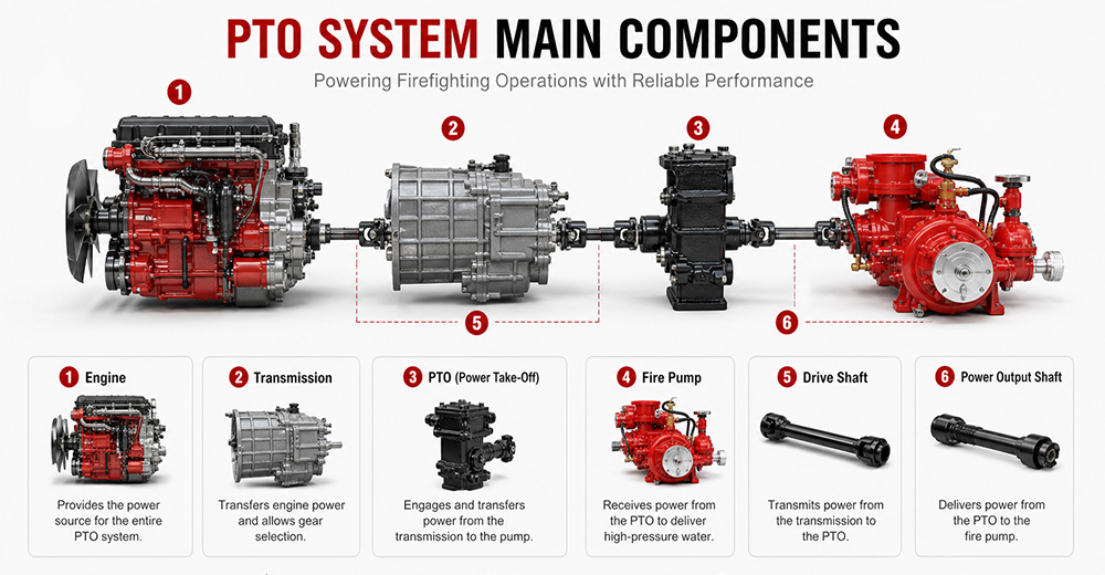
The fire pump is the final load of the PTO system, responsible for converting mechanical energy into water pressure energy.
Function: Receives rotational power from the PTO, drives the impeller to rotate, draws water in, and discharges it under high pressure.
Type: Centrifugal pump (single-stage, two-stage, or multi-stage).
Typical flow rate: 20 L/s – 180 L/s (1,200 – 6,000 L/min).
Typical pressure: 1.0 – 2.5 MPa (10 – 25 bar).
The PTO control system is the "command center" between the driver and the PTO system, responsible for engagement, disengagement, safety protection, and status indication.
Function: Controls PTO engagement and disengagement, monitors system status, and provides safety protection.
Operating location: Cab interior (primary control) and pump panel (auxiliary control).
Control methods: Manual cable, electric solenoid, pneumatic.
Specific control functions:
(1) PTO Engagement Control
The operator presses the PTO switch (electric solenoid/pneumatic) or pulls the lever (manual) in the cab. The control system sends a signal to engage the PTO's internal gears with the power source. After successful engagement is confirmed, an indicator light illuminates, allowing the operator to increase engine RPM.
(2) PTO Disengagement Control
The operator presses the switch again or resets the lever. The control system cuts the signal, and the PTO gears disengage. After disengagement is confirmed, the indicator light turns off.
| PTO Type | Installation Position | Power Source | Power Output | Typical Application |
| Sandwich PTO | Between engine and transmission | Engine flywheel | Full power (≥90%) | Fire pumpers, aerial trucks |
| Split-shaft PTO | Middle of chassis driveshaft | Transmission output shaft | Full power | Large vacuum trucks, airport fire trucks |
| Side-mounted PTO | Transmission side | Transmission gears | Partial power (lower) | Sprinkler trucks, small vacuum trucks |
Sandwich PTO
Advantages: Full power output (≥90%), supports "pumping while driving" (dual-function), high transmission efficiency, easy lubrication.
Disadvantages: Higher cost, complex installation, requires modification to the engine-transmission connection.
Split-shaft PTO
Advantages: Full power output, no additional space required, high reliability, good dynamic balance, can replace auxiliary engine to drive large pumps.
Disadvantages: Requires cutting the original driveshaft, installation position selection must consider driveshaft angle and length compensation.
Side-mounted PTO
Advantages: Low cost, simple installation, can draw power directly from the transmission side.
Disadvantages: Only partial power available, lower output torque, cannot drive high-power fire pumps, mainly used for low-speed, low-power equipment.
 for Fire Trucks")
The process follows a clear mechanical transmission chain:
Engine → PTO → Drive Shaft → Fire Pump → Impeller Rotation → Suction → Pressurization → Fire Monitor
| Factor | Role |
|---|---|
| Centrifugal pump characteristic | When impeller speed is constant, discharge pressure remains naturally stable |
| PTO rigid connection | No slippage or power loss, ensuring continuous stable power input |
| Pressure governor | Automatically detects flow changes and adjusts engine RPM to maintain set pressure |
| Relief valve | Automatically bypasses when pressure exceeds limit, preventing equipment damage |
① Pump speed is determined by engine RPM
Fire pump impeller speed = Engine RPM × PTO ratio. The PTO ratio is fixed (e.g., 1.75:1), so pump speed changes directly with engine RPM.
Calculation formula:
Engine RPM × PTO ratio = Pump speed (RPM)
② Physical relationship between pressure and speed
The pressure generated by a centrifugal pump is proportional to the square of the impeller speed. This physical law means that small changes in RPM cause significant pressure fluctuations.
Speed increases → Centrifugal force increases → Discharge pressure rises
Speed decreases → Centrifugal force decreases → Discharge pressure drops

1. PTO will not engage
Possible causes: Low air pressure (pneumatic type), faulty solenoid, damaged or stuck cable, interlock conditions not met (parking brake not applied, transmission not in neutral).
Solutions: Check air system pressure (must be ≥0.6 MPa); test solenoid; inspect cable; confirm parking brake is applied and transmission is in neutral.
2. PTO engages but pump does not work
Possible causes: PTO clutch failure, broken drive shaft or worn splines, damaged internal gears.
Solutions: Check PTO clutch engagement; inspect drive shaft for breakage or loose connections; disassemble and inspect internal gears.
3. PTO unusual noise
Possible causes: Poor gear meshing or wear, worn bearings, insufficient or degraded lubrication, PTO not fully disengaged.
Solutions: Check gear clearance and tooth wear; inspect bearings; replace with qualified lubricant; confirm PTO is fully disengaged.
4. PTO oil leakage
Possible causes: Worn or deteriorated seals, cracked housing, loose mounting bolts.
Solutions: Replace seals (O-rings, oil seals); inspect housing for cracks; tighten mounting bolts.
5. PTO overheating
Possible causes: Prolonged high-load operation, insufficient or degraded lubricating oil, cooling system failure.
Solutions: Reduce load or shut down for cooling; replace with qualified lubricant; inspect cooling lines.
6. PTO insufficient power
Possible causes: Improper PTO ratio selection, engine RPM set too low, clutch slippage.
Solutions: Confirm PTO ratio matches the fire pump; increase engine RPM to rated operating range; inspect clutch for slippage.
Q1. What does PTO stand for on a fire truck?
PTO stands for Power Take-Off. It is a mechanical system that transfers engine power from the truck's transmission to the fire pump. In simple terms, PTO allows the fire truck's engine to power the pumping system so it can deliver high-pressure water or foam for firefighting operations without needing a separate engine. It is a critical component in industrial and municipal fire trucks.
Q2. Why do fire trucks need a PTO?
Fire trucks need a PTO because it enables the vehicle's main engine to drive the fire pump efficiently. Without a PTO, the fire pump would require a separate engine, which increases cost, weight, and maintenance complexity. PTO systems provide a compact, reliable, and fuel-efficient way to ensure continuous water or foam supply during firefighting operations.
Q3. Can a fire truck operate without a PTO?
Most modern fire trucks cannot operate their pumping system without a PTO because the PTO is responsible for transferring engine power to the fire pump. However, some specialized fire vehicles may use an independent auxiliary engine to drive the pump. These designs are less common due to higher cost, increased maintenance, and lower efficiency compared to PTO-based systems.
Q4. What is the difference between PTO and a fire pump?
The PTO is a power transmission device, while the fire pump is a water or foam pumping system. The PTO delivers mechanical power from the engine to the pump, and the fire pump converts that power into hydraulic pressure to move water or foam. In short, PTO is the "power source connector," and the fire pump is the "firefighting output device."
Q5. How much power can a fire truck PTO provide?
The power output of a fire truck PTO depends on the vehicle design and transmission system. Typically, PTO systems can provide between 50 kW to over 300 kW of mechanical power. Heavy-duty industrial and airport fire trucks often use high-capacity PTO systems capable of supporting large-flow fire pumps and continuous high-pressure operations.
Q6. What are the different types of fire truck PTOs?
There are several types of fire truck PTO systems, including side-mounted PTO, rear-mounted PTO, split shaft PTO, and full power PTO. Side-mounted PTO is commonly used in standard fire trucks, while split shaft and full power PTO systems are used in industrial and airport fire trucks where higher power output and continuous operation are required.
Q7. How do you maintain a fire truck PTO?
PTO maintenance includes regular inspection of lubrication oil levels, checking for leaks, tightening mounting bolts, and ensuring proper alignment of the drive shaft. Operators should also test engagement and disengagement functions regularly. Preventive maintenance is essential to avoid overheating, mechanical wear, and unexpected failure during emergency operations.
Q8. What causes a fire truck PTO to fail?
Common causes of PTO failure include insufficient lubrication, worn gears, misalignment of the drive shaft, overheating, and improper operation by the driver. Electrical or hydraulic control system failures can also prevent PTO engagement. Regular maintenance and correct operating procedures significantly reduce the risk of PTO failure.
Q9. Which PTO is best for industrial fire trucks?
For industrial fire trucks, the best option is usually a split shaft PTO or full power PTO system. These systems can handle high power output, continuous operation, and large-capacity fire pumps. They are widely used in petrochemical plants, refineries, airports, and large industrial facilities where reliable and long-duration firefighting performance is required.
Q10. What should buyers consider when choosing a fire truck PTO?
Buyers should consider engine power compatibility, required fire pump flow rate, vehicle type, and working environment. It is also important to evaluate PTO durability, cooling performance, maintenance accessibility, and compatibility with the chassis. For export projects, compliance with international standards and local regulations should also be taken into account to ensure approval and operational reliability.
PTO (Power Take-Off) is the core system that transfers engine power to the fire pump — it determines whether the entire firefighting system can operate properly.
The fire truck power chain is: Engine → Transmission → PTO → Drive Shaft → Fire Pump → Fire Monitor. Any weak link in this chain affects final firefighting performance.
The primary function of the PTO is to provide stable, continuous mechanical power output, enabling the fire truck to deliver efficient water or foam supply without requiring a separate engine.
Different PTO types (Side-mounted, Rear-mounted, Split shaft, Full power) are suited to different fire truck classes. Industrial fire trucks typically prioritize high-power PTO systems.
PTO performance must match the fire pump flow rate and vehicle chassis, otherwise issues such as insufficient power, unstable pressure, or system overload may occur.
Regular PTO system maintenance (lubrication, tightening, alignment inspection) is key to ensuring reliable fire truck operation, especially in high-intensity industrial applications.
When purchasing industrial fire trucks, buyers should not focus solely on price. PTO power, stability, compatibility, and after-sales support are equally critical factors to evaluate.
For high-risk scenarios such as petrochemical plants, airports, and large industrial parks, Full Power PTO or Split Shaft PTO systems are recommended to ensure continuous operational capability.


Maaari kang maging interesado sa mga sumusunod na impormasyon
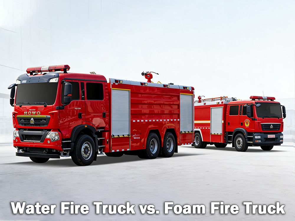
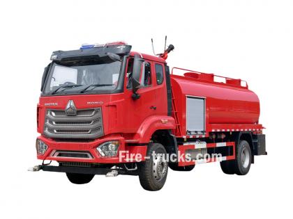
Mga trak ng bumbero na may tubig Patayin ang mga ordinaryong sunog na kinasasangkutan ng kahoy, papel, at tela. Ang mga foam fire truck ay pumapatay ng mga nasusunog na likidong apoy tulad ng gasolina at langis. Alin ang tama ay depende sa mga panganib na naroroon. Isang trak ng bumbero ng tubig Nagdadala ng malaking tangke ng tubig at umaasa sa isang high-pressure pump upang maghatid ng tubig sa pamamagitan ng mga hose o isang deck gun. Ito ang pinakakaraniwang uri ng trak ng bumbero na ginagamit ng mga departamento ng bumbero ng munisipyo at mga lugar na pang-industriya sa buong mundo. Isang trak ng bumbero na gawa sa foam Sa kabilang banda, ang foam ay espesyal na idinisenyo upang magdala at maghatid ng foam para sa pamatay-sunog. Kapag ang tubig lamang ay hindi kayang epektibong mapatay ang apoy — tulad ng sa mga nasusunog na likido, kemikal, o mga apoy na dulot ng panggatong — ang foam ang mas mainam na pagpipilian. Gumagana ang foam sa pamamagitan ng paglikha ng kumot sa ibabaw ng apoy, na pumipigil sa oxygen at pumipigil sa muling pagsiklab. I. Ano ang isang Water Fire Truck? Ang isang trak ng bumbero na gumagamit ng tubig ay eksakto kung ano ang tunog nito — isang sasakyan na may malaking tangke ng tubig, isang malakas na bomba, at mga hose o monitor upang maghatid ng tubig sa mga sunog. Ang tangke ng tubig ay karaniwang naglalaman ng nasa pagitan ng 500 at 3,000 galon (humigit-kumulang 2,000 hanggang 12,000 litro). Ang bomba ay kumukuha ng tubig mula sa tangke o mula sa isang panlabas na pinagmumulan tulad ng isang fire hydrant, lawa, o lawa-dagat, pagkatapos ay itinutulak ito sa mga hose sa ilalim ng mataas na presyon. Kung saan pinakamahusay na gumagana ang mga trak ng bumbero na may tubig: Ang mga water fire truck ay mainam para sa Mga sunog na Klase A , na kinabibilangan ng mga ordinaryong nasusunog na bagay: Kahoy at tabla Papel at karton Tela at tela Goma at plastik Damo, palumpong, at mga materyales sa kagubatan Kung ang sunog ay may kinalaman sa mga materyales na nasusunog sa isang bahay, bodega, o bukid, karaniwang tubig ang makakapatay nito. Mga Limitasyon ng Tubig: Ang tubig ay may isang malaking kahinaan. Kapag inispray sa mga nasusunog na likido tulad ng gasolina, langis, o mga kemikal, lumulubog ang tubig dahil mas mabigat ito kaysa sa mga panggatong na ito. Ang panggatong ay lumulutang sa ibabaw at patuloy na nasusunog. Sa ilang mga kaso, maaari pang kumalat ang apoy sa mas malawak na lugar. Kaya naman ang tubig lamang ay hindi epektibo para sa mga nasusunog na likido. Mga detalye ng bomba ng bumbero para sa trak ng bumbero: Trak ng bumbero na may tubig monitor ng sunog mga detalye: II. Ano ang Foam Fire Truck? Ang foam fire truck ay isang espesyal na sasakyan na idinisenyo upang maghatid at maghatid ng foam para sa pamatay-sunog. Nagdadala ito ng dalawang magkahiwalay na tangke — isa para sa tubig at isa para sa foam concentrate. Hinahalo ng foam proportioning system ang dalawa sa isang partikular na proporsyon, karaniwan...
Mga detalye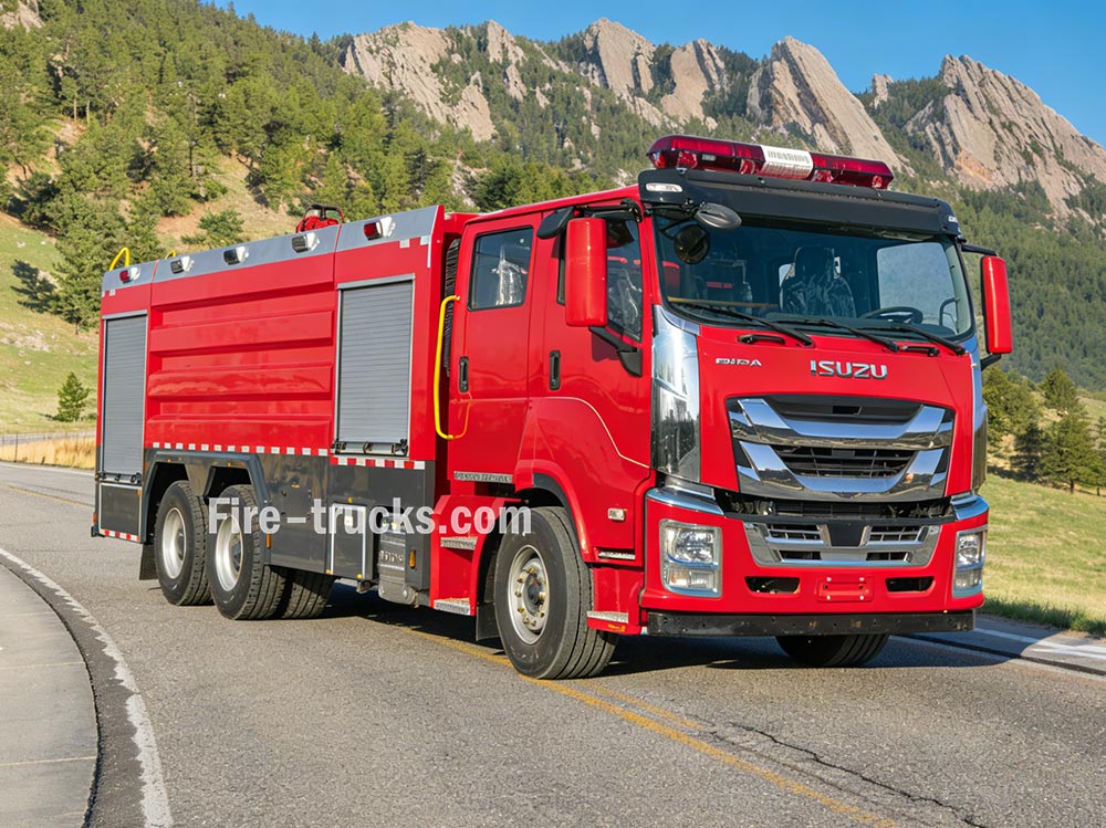
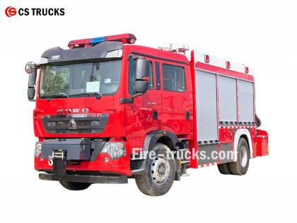
Mga trak ng bumbero gumana sa pamamagitan ng koordinadong tungkulin ng maraming sistema upang makamit ang suplay ng tubig, paglikha ng presyon, at pagsugpo sa sunog. Ang pag-unawa sa mga prinsipyong ito ay nakakatulong sa mga bumbero na gumana nang epektibo sa mga sitwasyong pang-emerhensya. » Ⅰ. Paano Gumagana ang mga Truck ng Bumbero: ▪ A. Sistema ng Bomba: Ang Puso ng Pagsugpo sa Sunog: Ang puso ng anumang trak ng bumbero ay ang bomba nito. Ang high-powered unit na ito ay kumukuha ng tubig mula sa tangkeng nasa loob o mula sa panlabas na pinagmumulan—tulad ng fire hydrant, lawa, o lawa-dagat at dinadala ito sa pamamagitan ng mga hose sa ilalim ng mataas na presyon. Ang pinakakaraniwang ginagamit na bomba ay ang centrifugal pump, na umaasa sa isang umiikot na impeller upang mag-pressurize at magpagalaw ng tubig. Kinokontrol ng mga bumbero ang daloy ng tubig gamit ang isang serye ng mga pingga at gauge sa pump panel. Maaari nilang isaayos ang presyon kung kinakailangan at idirekta ang tubig sa maraming linya ng hose nang sabay-sabay. Uri ng Bomba Mga Katangian Pinakamahusay na Aplikasyon Isang yugto ng sentripugal na bomba Mataas na daloy, katamtamang presyon Pangkalahatang pag-apula ng sunog sa munisipyo Dalawang-yugtong sentripugal na bomba Maaaring lumipat sa pagitan ng volume at pressure Matataas na gusali, mahahabang hose ang nakalatag Bomba na may maraming yugto Napakataas na presyon Mga pasilidad pang-industriya, mga sistema ng foam ▪ Mga Pangunahing Parametro ng Bomba: › Bilis ng daloy: 1,200 - 6,000 litro kada minuto (depende sa modelo) › Pinakamataas na presyon: 1.0 - 2.5 MPa (10-25 bar) › Oras ng pag-prim: ≤30 segundo ▪ B. Tangke ng Tubig at Sistema ng Imbakan: › Kapasidad ng tangke: 500 - 1,500 galon (humigit-kumulang 2,000 hanggang 6,000 litro), depende sa laki at uri ng sasakyan › Materyal ng tangke: Hindi kinakalawang na asero na lumalaban sa kalawang o pinahiran na carbon steel › Mga panloob na baffle: Maraming kompartamento na may disenyong anti-surge upang makontrol ang paggalaw ng tubig sa panahon ng pagtugon sa emergency › Oras ng pagpuno: ≤3 minuto sa pamamagitan ng fire hydrant o drafting › Tagapagpahiwatig ng antas ng tubig: Biswal na panukat sa gilid ng tangke; opsyonal na display ng kabin Ang tangke ay gawa sa mga materyales na lumalaban sa kalawang, karaniwang hindi kinakalawang na asero o pinahiran ng carbon steel, na may mga panloob na baffle plate na kumokontrol sa pag-agos ng tubig sa panahon ng pagtugon sa emergency. ▪ C. Mga Sistema ng Hose at Nozzle Ang mga trak ng bumbero ay may iba't ibang hose na may iba't ibang gamit: › Hose para sa pag-atake: 1.5 - 2.5 pulgada ang diyametro — direktang naghahatid ng tubig sa pinagmumulan ng apoy › Hose ng suplay: 4 - 5 pulgada ang diyametro — naghahatid ng tubig mula sa mga hydrant o iba pang mga pumper › Booster hose: maliit na diyametro sa reel — ginagamit para sa maliliit na sunog tulad ng sunog sa damo o sasakyan Sa dulo ng hose, ang nozzle ay nagbibigay-daan sa mga bumb...
Mga detalye
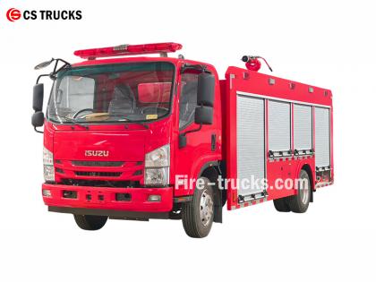
Bilang pinaka-propesyonal na pabrika ng trak ng bumbero ng Isuzu, ang pangunahing disenyo ng trak ng bumbero ng Isuzu NPR water foam ay ang pagsasama ng isang sistema ng pamatay-sunog na foam sa isang trak ng bumbero ng water tanker, na bumubuo ng isang composite na kagamitan sa pamatay-sunog na kayang mag-spray ng tubig at foam. Kaya nitong mag-isa na patayin ang apoy; maghatid ng pinaghalong tubig o foam sa iba pang kagamitan; at angkop para sa mga operasyon sa mga lugar na tuyot at mahirap maubos ang tubig. ★ Teknikal Espesipikasyon Lahat ng trak ng bumbero mula sa mga trak ng CS, 100% batay sa mga kinakailangan ng customer Kapasidad Modelo ng makina Tubig Foam Bomba ng Sunog Tagasubaybay ng Sunog 2,500L ISUZU 4HK1 / 19 0HP 2,500L 500L Bomba ng Sunog ng CB10/40 PL8/32 2026 opisyal na ISUZU trak ng bumbero na may cab chassis truck 2026 orihinal na drowing ng tsasis ng trak ng bumbero Aytem Mga Detalye ng Disenyo ng mga trak ng bumbero ng Isuzu Disenyo ng Core Pinagsasama ang isang foam extinguishing system sa isang water tanker fire truck, na bumubuo ng isang dual-capability fire-fighting vehicle na may kakayahang maglabas ng tubig at foam. Kabilang sa mga tampok ang: • Malayang pagsugpo sa sunog • Suplay ng tubig o pinaghalong foam sa iba pang kagamitan • Angkop para sa mga lugar na tuyot o mahirap tubig, na nagbibigay-daan sa maraming gamit Pangkalahatang Konsepto ng Disenyo Dinisenyo upang matugunan ang mga pangangailangan sa pag-apula ng sunog sa mga workshop at mga nakapalibot na lugar, na may pinahusay na kakayahan para sa sunog sa langis, elektrikal, at solidong materyal; ang sasakyan ay binubuo ng isang tsasis at espesyal na kagamitan sa katawan, na nagbibigay-diin sa pagiging maaasahan, maraming gamit, at kadalian ng operasyon. Pagpili ng Tsasis • Gumagamit ng napatunayang medium o heavy-duty type-II chassis • Inirerekomenda ang all-wheel drive upang mapabuti ang kadaliang kumilos at traksyon sa masalimuot na lupain BAGONG DISENYO NG ISUZU 700P Water Fire Truck 2026 Mga Pangunahing Bahagi at Disenyo ng Sistema 1. Tangke ng Tubig at Tangke ng Likidong Foam • Materyal: Hindi kinakalawang na asero, lumalaban sa kalawang • Inirerekomendang kapasidad: Tangke ng tubig 3000–5000L, tangke ng foam liquid 300–600L • Pag-optimize sa istruktura: Pinaghihiwalay ng mga panloob na baffle ang mga silid ng tubig at foam, maaaring ilipat sa pamamagitan ng pagkonekta ng mga port sa single water tank mode, na nagbibigay-daan sa paggamit na maraming gamit 2. Sistema ng Pagproporsyon ng Foam • Gumagamit ng balanced pressure proportioner (pangunahing bahagi) upang tumpak na paghaluin ang tubig at foam concentrate sa 3% o 6% na ratio • Matatag na output na hindi naaapektuhan ng mga pagbabago-bago ng daloy o presyon, angkop para sa mga hindi espesyalistang operator • Nilagyan ng panlabas na foam suction inlet para sa on-site replenishment 3. Sistema ng Paglabas • Bomba ng bumbero: Mataas na kahusayan, nakakatipid ng enerhiya na multi-stage centrifugal pump, fl...
Mga detalye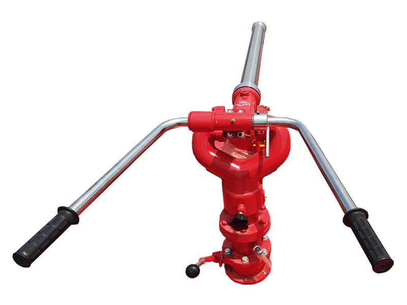
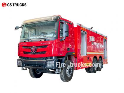
Ang PF5-15 nakapirming monitor ng tuyong pulbos Gumagamit ng tuyong pulbos bilang midyum at umaasa sa isang nakapirming base para sa matatag na pag-ispray. Ito ay angkop para sa mga lugar ng kemikal at bodega, at mabilis na kayang takpan ang nasusunog na ibabaw sa mga unang yugto ng sunog, na nagpapabuti sa kahusayan ng pag-apula. Ang PF5-15 nakapirming monitor ng tuyong pulbos ay may matibay na istruktura, madaling gamitin, at maaaring ikonekta sa isang awtomatikong sistema ng kontrol para sa malayuang pag-activate at tumpak na pag-spray. » Ika-1. PF5-15 nakapirming monitor ng tuyong pulbos istruktura: Mga Katangian ng PF5-15 fixed dry powder monitor: ● Ganap na gumagana; ● Simple at makabagong istruktura; ● Matatag na pagganap at madaling pagpapanatili; ● Mababang presyon ng pasukan; ● Nilagyan ng awtomatikong balbula ng paagusan na may pahalang at patayong mga function ng pagla-lock; ● Materyal: Haluang metal na aluminyo na gawa sa katumpakan; ● Ulo ng kanyon: Haluang metal na aluminyo. » Ikalawa. Foam Cannon PL24 mga detalye: Modelo Daloy ( kilo /s ) Saklaw ( m ) Na-rate na presyon ng pagtatrabaho ( Mpa ) Pag-ikot ng pitch ( ° ) Pahalang na pag-ikot ( ° ) P×L×T ( milimetro ) Timbang ( Kilogram ) PF5-15/40 40 ≥42 0.80 -45 ~ +70 0 ~ 360 980x340x550 28.5 » Ika-3. Mga Aplikasyon ng Produkto: Trak ng bumbero na may PF5-15 na nakapirming monitor ng tuyong pulbos Pagsubok sa PF5-15 na nakapirming dry powder monitor Ang PF5-15 fixed dry powder monitor ay may mahabang distansya ng pag-ispray at malawak na sakop, at mabilis na nakakabuo ng harang sa pamatay-sunog na dry powder. Ito ay angkop para sa mga nakapirming lokasyon tulad ng mga planta ng kemikal, mga depot ng langis, at mga lugar ng imbakan, na nagbibigay ng tuluy-tuloy at matatag na kakayahan sa pamatay-sunog para sa malalaking lugar.
Mga detalye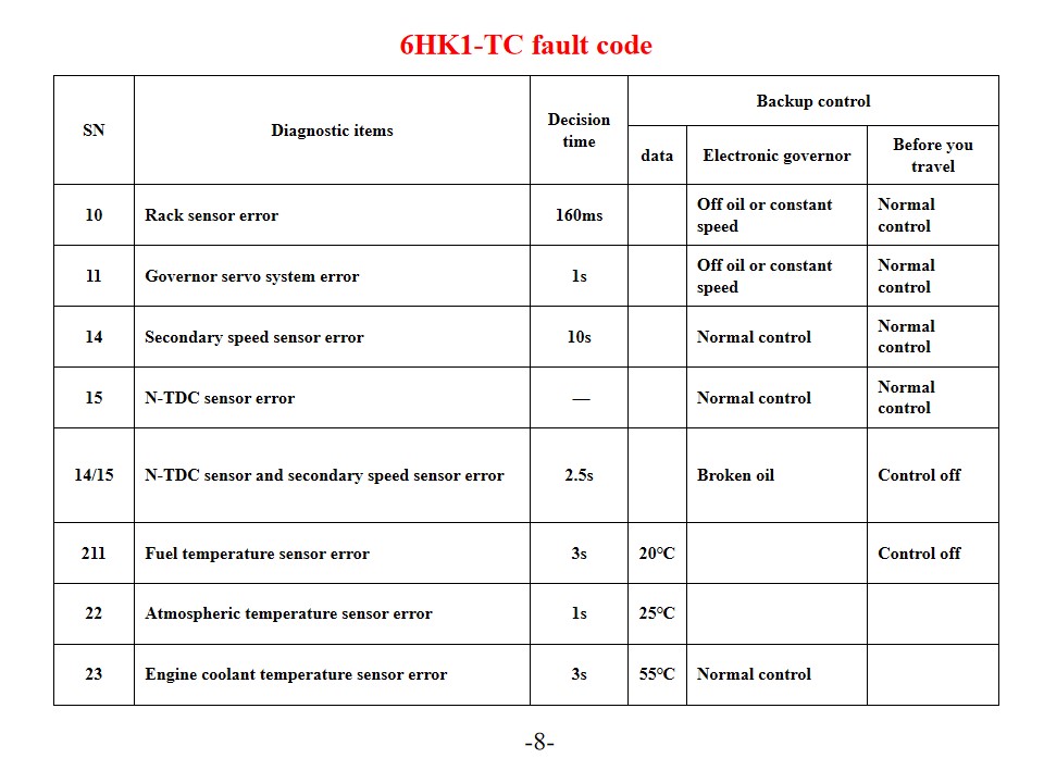
Mga trak ng bumbero ng Isuzu 6HK1-TC , pinangalanan din Sasakyang pang-rescue bumbero ng Isuzu , Pagsusuri at mga Solusyon sa Error Code ng Makina. Ang makinang Isuzu 6HK1-TC ay gumagamit ng makabagong TICS fuel injection pump electronic control system, at ang ECU (Engine Control Unit) ay may self-diagnosis. Kapag nakakita ang sistema ng depekto, ang "CHECK ENGINE" warning light ay umiilaw at ang kaukulang fault code ay iniimbak. Ang pag-unawa sa interpretasyon at mga solusyon para sa mga error code na ito ay maaaring epektibong mapabuti ang kahusayan sa pagpapanatili ng makina. Mga Karaniwang Error Code at Solusyon Mga Kodigo ng Problema sa P-Series P0101 (Mababang Circuit ng Sensor ng Daloy ng Mass Air) Suriin ang sensor ng temperatura ng coolant ng makina at ang mga kable nito. Tiyakin ang boltahe ng power supply ng sensor at koneksyon sa ground. Palitan ang ECU o sensor kung kinakailangan. P0102 (Mataas na Circuit ng Sensor ng Daloy ng Mass Air) Suriin ang kalidad ng gasolina at kondisyon ng filter. Linisin ang sistema ng gasolina. Suriin ang fuel pressure regulator, fuel pump, at mga injector circuit. P0103 (Mass Air Flow Sensor A Circuit High) Suriin ang sensor signal circuit para sa short circuit. Subukan ang operating status ng sensor. Palitan ang sensor o ECU kung kinakailangan. Mga Digital na Kodigo ng Problema 10 (Error sa Sensor ng Rack) Suriin ang rack sensor at ang mga kable nito. Tiyakin ang normal na transmisyon ng signal. 11 (Error sa Sistema ng Servo ng Speed Governor) Suriin ang katayuan ng pagpapatakbo ng speed governor servo system. Subukan ang mga kaugnay na koneksyon ng circuit. 14 (Error sa Sensor ng Bilis ng Pantulong) Suriin ang posisyon ng pagkakabit ng auxiliary speed sensor. Subukan ang signal output ng sensor. 15 (Error sa Sensor ng N-TDC) Suriin ang koneksyon ng sensor ng N-TDC I-verify ang katumpakan ng signal Pagpapanatili ng sistema at mga hakbang sa pag-iwas SN Mga bagay na pang-diagnostic Oras ng pagpapasya Kontrol sa pag-backup datos Elektronikong gobernador Bago ka maglakbay 10 Error sa sensor ng rack 160ms Walang langis o pare-parehong bilis Normal na kontrol 11 Error sa sistema ng servo ng gobernador 1s Walang langis o pare-parehong bilis Normal na kontrol 14 Error sa pangalawang sensor ng bilis 10s Normal na kontrol Normal na kontrol 15 Error sa sensor ng N-TDC — Normal na kontrol Normal na kontrol 14/15 Error sa sensor ng N-TDC at pangalawang sensor ng bilis 2.5s Sirang langis Kontrolin ang naka-off 211 Error sa sensor ng temperatura ng gasolina 3s 20℃ Kontrolin ang naka-off 22 Error sa sensor ng temperatura ng atmospera 1s 25℃ 23 Error sa sensor ng temperatura ng coolant ng makina 3s 55℃ Normal na kontrol Konektor Numero ng Terminal Senyales Diyametro/kuryente ng alambre (Gamit ng bombang pang-injeksyon) SWP 8-terminal Itim 1 Boltahe ng drive ng actuator ng gobernador - 1 RM2 2 Sirkito ng Gobernador GND-1 Sa 1.2 3 Posisyon ng target rack - 1 U1 2 4 Boltahe sa posisyon ng rack G/1.2 5 Sirkito ng gobernado...
Mga detalye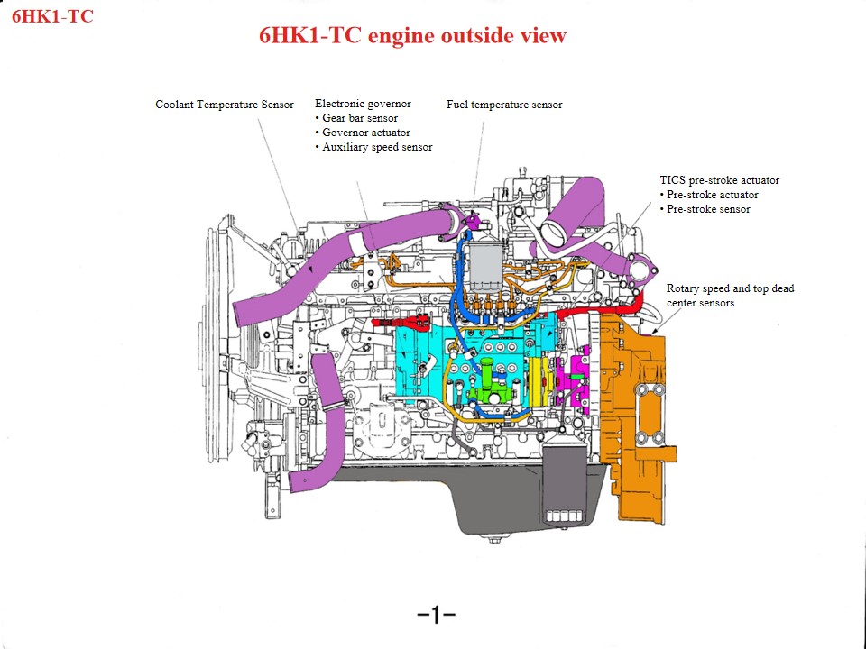
Mga Sasakyang Pang-rescue sa Bumbero ng Isuzu 6HK1 , pinangalanan din Trak ng bumbero ng Isuzu , Kung mag-overheat ang makina ng isang Isuzu rescue fire truck, dapat munang suriin ang mga sumusunod na bahagi: 1. Sistema ng pagpapalamig: Ang mga problema tulad ng sirang bentilador, baradong radiator, sirang thermostat, o hindi sapat na coolant ay maaaring mag-ambag sa sobrang pag-init ng makina. 2. Kalidad at dami ng langis: Ang mahinang kalidad ng langis o hindi sapat na langis ay maaari ring maging sanhi ng sobrang pag-init ng makina. 3. Ang mga mekanikal na pagkabigo tulad ng pagsabog ng silindro, mga bitak ng cylinder liner, o mga bitak ng cylinder liner ay maaari ring maging sanhi ng hindi pangkaraniwang bagay na ito. Bilang isang heavy-duty diesel powertrain, ang Isuzu 6HK1 engine ay nangangailangan ng mahigpit na pagsunod sa mga teknikal na detalye para sa pagpapanatili. Ang mga pangunahing punto ay ang mga sumusunod: 1. Pag-unawa sa Istruktura at mga Espesipikasyon ng Pagbubuklod at Pag-assemble Mekanismo ng Crankshaft-Connecting Rod Ang cylinder liner ay may maluwag na disenyo, na nangangailangan ng mga espesyal na kagamitan upang maiwasan itong mahulog habang binabaklas at ina-assemble. Ang karaniwang clearance ay 0.122–0.156mm. Ang panlabas na diyametro ng piston ay may mahigpit na tolerance (114.894–114.909mm). Habang nagkakabit, bigyang-pansin ang direksyon ng pagbukas ng piston ring at ang pagsasaayos ng "tatlong clearance" (end clearance, side clearance, at back clearance). Ang ibabang crankcase ay isang piraso lamang na istraktura at dapat itaas habang isinasagawa ang maintenance upang maiwasan ang deformation. Pag-align ng Sistema ng Timing Habang ina-assemble ang gearbox, ihanay ang mga marka ng crankshaft gear at idler gear. Ang marka ng camshaft B ay dapat na kapantay ng ibabaw ng cylinder head. Ang makina ay dapat nasa compression top dead center sa unang cylinder. Kapag ikinakabit ang fuel injection pump, ihanay ang timing pointer sa S point sa connector, at ihanay ang injection advancer mark sa pump body pointer. • Itinutulak ng linear DC motor ang coil pataas at pababa sa ilalim ng signal ng output ng control unit. • Ang connecting rod na nakakabit sa coil assembly ay nagpapadala ng pataas at pababa na galaw ng coil papunta sa connecting block, at ang connecting block ay naka-install sa dulo ng rack. Sa ilalim ng pagtulak ng connecting block, ang rack ay gumagalaw pakaliwa at pakanan upang baguhin ang dami ng fuel injected. Kapag ang coil assembly ay gumagalaw pataas, ang link ay itinutulak ang rack upang pataasin ang direksyon ng langis; sa kabaligtaran, kapag ang coil assembly ay bumaba, ang rack ay gumagalaw sa direksyon ng pagbabawas ng langis, at ang tungkulin ng column ay i-convert ang patayong galaw sa taas ng galaw ng rack. • Ang bloke ng tanso ay nakakabit sa itaas na bahagi ng bloke ng pangkonekta upang bumuo ng isang rack sensor. Natutukoy ng rack sensor ang rack stroke at ipinapadala ang halagang ito pabalik sa ...
Mga detalye
Mangyaring magpatuloy sa pagbabasa, manatiling nakaantabay, mag-subscribe, at malugod naming hinihintay ang inyong mga komento.

 Suportado ang network ng IPv6

 Filipino
 English
 français
 Deutsch
 русский
 italiano
 español
 português
 Nederlands
 العربية
 日本語
日本語 한국의
한국의 Türkçe
 Melayu
 ไทย
ไทย Tiếng Việt
 Indonesia
  中文
中文 қазақ
қазақ မြန်မာ
 српски